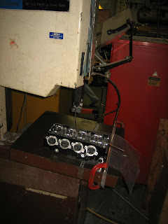
After working on all these engine parts I got a bug to shift focus and to make some inroads on the pile of chassis parts that need to be made. My first choice was to make the upright legs for the front suspension. These legs are central to the variable flex idea that is incorporated in the front suspension. Instead of following the current ideas on overall bike flexibility which uses stiff telescopic forks and a slightly flexible chassis, I prefer to have the flex where it is needed-at the wheel. Telescopic fork equipped bikes don't have much of an option here- the forks needs to be relatively rigid, otherwise they would bind up when flexing under braking load, preventing smooth suspension movement. With the linkage suspension I am using it is possible to have a very stiff chassis and a-arm structure to allow smooth suspension action and accurate wheel location yet have flex built into the upright legs to accommodate small bumps and irregularities in the surface when leaned far over.
From the years spent campaigning my
single cylinder racer I have a good idea of the directional stiffness that will produce good results. No, I won't go into specifics here on what the stiffness ratios are. As expected, maximum stiffness is needed in the braking direction and much less needed in the transverse direction. The initial uprights I designed worked well, but was a bit complex to make quick copies of. I then moved on to a much simpler design using rectangular steel, some with welded on stiffening plates to tweak the stiffness as testing dictated. The latest version of the front suspension uses some old and some new to result in a low friction assembly with easily characterized controlled flex characteristics.
First upright design using suspended headstock design:
This design worked very nicely but was a bit complex to make variations on. The suspended headstock and all ball bearing upright mounts provided smooth action and good feel but at a weight penalty to later, simpler designs.
Second design style using spherical bearings (bearings not shown):
This design had the benefit of being easy to replicate with subtle stiffness variations but I found the spherical rod end bearings reduced feel and required frequent replacement in order to maintain optimum performance.
Final version for the V4 project bike:
This version separates the parts into a bearing carrier and legs that bolt on. It enables easy modifications to the stiffness by making new leg parts with varying dimensions yet keeps the bearing mount arrangement stiff. The weight is in between the first two designs, a good overall compromise in my opinion. The upright legs will be machined today.
As with most billet parts I started with a large plate that both parts could fit in. I bolted this directly to the CNC table and machined the mounting pads and axle holes as shown in the following image:
I then machined a fixture baseplate that would locate on these premachined features and allow me to complete the part:
The fixture locates on the machine table with dowel pins allowing easy and accurate setup for making more parts.
I then cut out the individual parts leaving extra stock around the perimeter and bolted them to the fixture plate as shown:
Next came the pocketing and chamfer operations:
Resulting in a sweet looking part:
Mirroring the toolpaths allowed me to create the 2nd part with a minimum of hassle resulting in a very stiff looking assembly: This design also makes use of the latest radial mount Brembo billet calipers for the ultimate in progressive braking feel.
I don't mention it often enough so a big thank you goes out my shopmate to
Peter H. for allowing me essentially unlimited use of his 4 axis CNC mill. Without access to his machine I'd be making much lower quality parts on my old BP 3 axis relic. And I'd still be figuring out how to fit the engine castings on it!
In the next few days I hope to move on to the upright bearing housing and handlebar mount, both of which need the 4th axis and trunnion table.
Until then.....


