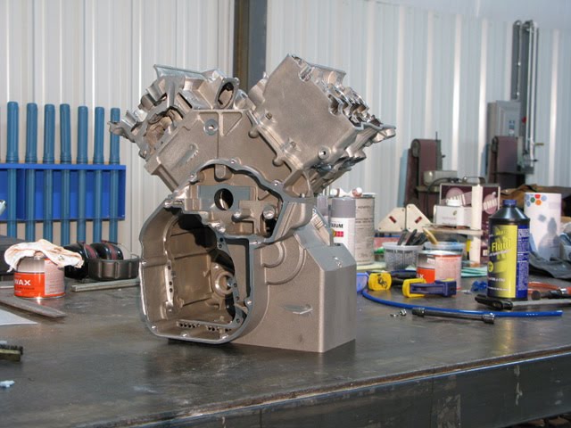
Just posting a few shots of the various parts that are accumulating. It's nice to start a project like this and have spare parts available to experiment with. Previous bike and engine projects have been one-offs and that presents a problem when failure is encountered- the need to wait for a replacement custom part, usually the weekend before a race! Now we'll have the ability to have 2 complete engines plus a host of spare parts. What luxury!
Most of the parts are produced to my specifications by the indicated vendor, the rest are standard aftermarket performance parts. Thanks to Barry from Celtic Racing for referring us to Skip Dowling of Orient Express, a great source for all things OEM and aftermarket in the SportBike world. Skip was able to get us the parts we need at very reasonable prices. A shout also goes out to Fred Renz of Yoyodyne, a great resource for hard to get exotic parts and just about anything Brembo manufacturers, even the true GP equipment.
Castings: a lot has been said about these parts and the great job Harmony/TPI is doing so I'll leave it at that.
Chassis Castings: great parts from Harmony/TPI here too.
J&E Pistons: producer of top quality pistons for motorsports. These are a high compression version of their ZX6-R product.
Carrillo connecting rods: What is there to say? If you want the best rod, you buy a Carrillo.
Oil pump gerotor and custom drive gears: fron Melling and SDP-SI, respectively.
Tungsten crank counterweights: From Midwest Tungsten Service. These bolt on counterweights that nest inside the con rod I beam area help keep crank and overall engine cases as narrow as possible.
Brembo front brake calipers and master cylinder from Yoyodyne: Again, if you want the best, you get Brembo.
Ohlins TTX front damper from Motorsports Spares, who usually deal with 4 wheel vehicles, but had the knowledge of the generic Ohlins components to help us source a suitable solution for our front spring/damping needs.
Cometic gaskets:
Lots of misc bolts, seals, bearings, etc.
More misc parts, mostly from Orient Express:
I'm starting to amass quite a collection of parts. Soon this chaotic jumble of parts will defy entropy and assemble into an organized machine capable of scorching the track.
That's all for now.
Monday, September 27, 2010
Flip-Flopping the Crankshaft
We've made good progress on the crank so far, one aluminum test part and 3 final steel parts all have the first lathe operation complete with no crashes, broken tools, or other mishaps.
Now we remove the 3 jaw chuck front he lathe and replace it with a 16C collet nose. The collet nose will allow us to hold the part very accurately from a previously machined feature. We'll then indicate the length of the part and run the second lathe operation. This operation creates the features for the generator main bearing journal, the front bank cam drive, and the tapered stator mount.
3 jaw chuck in first lathe operation:
16C collet nose for second operation:
Now just a few button presses and the 2nd operation is finished:
Repeatedly running the program finishes out the parts for now:
Now we are finished with the lathe work. Next up will be putting the parts in the 4th axis on the mill and creating the 2 sets of offset throws for the connecting rods and the sprocket teeth for the cam chain drives. once those features are complete I'll put the part up on a manual mill and drill and deburr the main and rod bearing oil holes. Unfortunately, that will need to wait a week or so for some client work on the mill to be finished.
Now we remove the 3 jaw chuck front he lathe and replace it with a 16C collet nose. The collet nose will allow us to hold the part very accurately from a previously machined feature. We'll then indicate the length of the part and run the second lathe operation. This operation creates the features for the generator main bearing journal, the front bank cam drive, and the tapered stator mount.
3 jaw chuck in first lathe operation:
16C collet nose for second operation:
Now just a few button presses and the 2nd operation is finished:
Repeatedly running the program finishes out the parts for now:
Now we are finished with the lathe work. Next up will be putting the parts in the 4th axis on the mill and creating the 2 sets of offset throws for the connecting rods and the sprocket teeth for the cam chain drives. once those features are complete I'll put the part up on a manual mill and drill and deburr the main and rod bearing oil holes. Unfortunately, that will need to wait a week or so for some client work on the mill to be finished.
Saturday, September 25, 2010
I Love CNC
The wonders of modern technology.
From:
To this:
In a couple of hours. All the parts are accurate to within a few ten thousandths of an inch.
The switch from the 2024 aluminum test material to the 4340 steel part material required slowing the cutting speed by approximately 50% and increasing the feed rate by 25%. It may seem counter intuitive to increase the feed rate for a stronger material but the carbide insert's cutting edge needs to be able to get a decent bite into the material, otherwise it just deflects the workpiece and rubs, causing a lot of heat buildup and usually insert/tool failure which leads to a scrapped part.
Now that all 3 initial pieces are machined I will change the setup in the lathe to flip the part around and accurately hold it by the features we just machined. That post will be up soon.
From:
To this:
In a couple of hours. All the parts are accurate to within a few ten thousandths of an inch.
The switch from the 2024 aluminum test material to the 4340 steel part material required slowing the cutting speed by approximately 50% and increasing the feed rate by 25%. It may seem counter intuitive to increase the feed rate for a stronger material but the carbide insert's cutting edge needs to be able to get a decent bite into the material, otherwise it just deflects the workpiece and rubs, causing a lot of heat buildup and usually insert/tool failure which leads to a scrapped part.
Now that all 3 initial pieces are machined I will change the setup in the lathe to flip the part around and accurately hold it by the features we just machined. That post will be up soon.
Wednesday, September 22, 2010
Machining Step 1 on the Lathe
After a couple of long days and late nights machining non-motorcycle parts the lathe is open and I can run a test part of the first crankshaft program! I'm making the first part from some scrap 2024 aluminum to verify the program before using the more expensive and much harder to machine 4340 steel material.
The machining process will be:
This is taken after the finishing of the main profile:
And this is taken after the program is complete:
Here's some CAD vs reality for a comparison:
The aluminum version looks nice but would never be able to withstand the temperature and stress of operation. Next up is the 2nd machining operation that finishes the opposite end main bearing and tapered generator mount. After that operation the part will move to the mill for some 4 axis work on the conrod journals and camdrive sprocket teeth.
Until the next update......
The machining process will be:
- drill 60 degree center in outer end for tailstock support
- roughing the main profile
- finishing the main profile
- machining small undercuts on main profile
- machine center main bearing fearure
- remove as much conrod journal stock as possible
This is taken after the finishing of the main profile:
And this is taken after the program is complete:
Here's some CAD vs reality for a comparison:
The aluminum version looks nice but would never be able to withstand the temperature and stress of operation. Next up is the 2nd machining operation that finishes the opposite end main bearing and tapered generator mount. After that operation the part will move to the mill for some 4 axis work on the conrod journals and camdrive sprocket teeth.
Until the next update......
Monday, September 20, 2010
Programming Setup 1 on the Lathe
The first step in converting CAD to chips is to plan ahead, and it should happen very early in the design stages, otherwise you run the risk of having an unmachinable or hard to machine part. What we are doing here is step 2, converting 3D CAD to 2D CAD to G-code CAM. The 3D CAD provides complete surface information of the part. Since at this stage the part is a simple revolved shape, we can reduce it to a 2D profile and not lose any information about the shape. From this 2D profile the CAM software creates a series of 2 dimensional moves along the X axis (diameter) and Z axis (length of part) that create the part profile from solid bar using appropriate cutting speeds and feeds.
3D CAD:
2D CAD:
2D CAM:
Now we can go to the machine, which is currently busy.....
The CAM package is told the shape and position of the various tools needed to cut the part, it is told the shape of the part, and it is told the characteristics of the machine. Doing what computers do well, crunch numbers, it uses all of this hopefully accurate information to calculate the appropriate motions to generate the desired part profile. As with all computer programs, garbage in=garbage out, except instead of the BSOD or an inaccurate spreadsheet, you get twisted metal and a large repair bill. It is a very good incentive to make sure all the info input is correct and also carefully check the output. The output of this 2D CAM process is a text file in what machinists call a G-code format. A sample g-code file in a format usable by my Siemens control looks like this:
%MPF52
G70 G90 G40 G54
(TOP-CAP-3-rec2-rad PR=3.745 Z1=8.075 )
(T-2 O-6)
(DCGX IN SDJCR-123)
T02 D06
G0 X0.825 Z.5
Z0.
M3 S1000
G96 S1000
M8
G1 X-0.0357 F.005
G0 X0.6316 Z.155
G96 S1500
G1 Z-2.99 F.008
X0.6864
G0 Z.11
X0.5567
G1 Z-2.4417
X0.5625 Z-2.4475
G3 X0.57 Z-2.4656 B.0256
G1 Z-2.99
The format is relatively simple and once you have used it a bit reading it is pretty straightforward. The G-Code file is sent to the machine over the network and then after machine setup the program is run.
Once my current lathe job is complete the crank goes right in. I hope to have another blog update sometime this week.
3D CAD:
2D CAD:
2D CAM:
Now we can go to the machine, which is currently busy.....
The CAM package is told the shape and position of the various tools needed to cut the part, it is told the shape of the part, and it is told the characteristics of the machine. Doing what computers do well, crunch numbers, it uses all of this hopefully accurate information to calculate the appropriate motions to generate the desired part profile. As with all computer programs, garbage in=garbage out, except instead of the BSOD or an inaccurate spreadsheet, you get twisted metal and a large repair bill. It is a very good incentive to make sure all the info input is correct and also carefully check the output. The output of this 2D CAM process is a text file in what machinists call a G-code format. A sample g-code file in a format usable by my Siemens control looks like this:
%MPF52
G70 G90 G40 G54
(TOP-CAP-3-rec2-rad PR=3.745 Z1=8.075 )
(T-2 O-6)
(DCGX IN SDJCR-123)
T02 D06
G0 X0.825 Z.5
Z0.
M3 S1000
G96 S1000
M8
G1 X-0.0357 F.005
G0 X0.6316 Z.155
G96 S1500
G1 Z-2.99 F.008
X0.6864
G0 Z.11
X0.5567
G1 Z-2.4417
X0.5625 Z-2.4475
G3 X0.57 Z-2.4656 B.0256
G1 Z-2.99
The format is relatively simple and once you have used it a bit reading it is pretty straightforward. The G-Code file is sent to the machine over the network and then after machine setup the program is run.
Once my current lathe job is complete the crank goes right in. I hope to have another blog update sometime this week.
Sunday, September 19, 2010
Starting on the Crankshaft
Now that the engine case patterns are approved and the production order placed I can move on to the crankshaft.
It will be a 180 crank to exploit the reduced variations in reflected crankshaft inertia that this configuration provides, similar to Yamaha's cross plane crank in the M1 Grand Prix bike and the R1 Super Bike.
I will be initially testing 2 different versions of the crank- one with pork chop counterweights and one with full circle counterweights. The main testing variable is the overall weight/inertia vs. aerodynamic efficiency of the 2 versions.
Full circle configuration:
Pork Chop configuration:

The manufacturing process will be as follows:
Material blank:
The process will involve 2 lathe setups and one milling setup.
The lathe first lathe setup will hold a 3 3/4" x 9.5" long material blank in a 3 jaw chuck. we'll machine one end of the crank, the middle main bearing journal, and various smaller features on one end of the part.
End of first lathe setup:

Once I finish some client lathe work currently running this is next in line. The next post will detail programming and cutting of this first lathe operation.
It will be a 180 crank to exploit the reduced variations in reflected crankshaft inertia that this configuration provides, similar to Yamaha's cross plane crank in the M1 Grand Prix bike and the R1 Super Bike.
I will be initially testing 2 different versions of the crank- one with pork chop counterweights and one with full circle counterweights. The main testing variable is the overall weight/inertia vs. aerodynamic efficiency of the 2 versions.
Full circle configuration:
Pork Chop configuration:
The manufacturing process will be as follows:
Material blank:
- 3 3/4" diameter x 9.7" long
- 4340 steel
- 28-32 Rockwell C hardness
- Machine crank on lathe in 2 steps blank leaving .01-.02 stock on surfaces to be ground.
- Mount lathe blank in mill 4th axis and rough machine crank throws
- Rough and finish machine the two silent chain cam drive sprockets with custom form end mill cutters.
- Hobbing of primary drive gear and starter clutch/crank sensor spline will be done by Eagle Machine, Inc. of British Columbia. They have experience to properly deail with custom low production crankshaft.
- Final Grinding of main and rod bearing surfaces will be done by Lopez Crank Shaft of Santa Fe, CA. They are another custom crank specialist and can provide the accuracy and surface finish needed.
- Plasma nitriding will be done by Accurate Ion Technologies, a specialist in steel hardening and advanced surface finishes. We are using plasma nitriding for it's low process temperature that enables proper multilayer surface hardening of the part with no distortion.
- Once we get the part back from Accurate Ion it is ready for use.
The process will involve 2 lathe setups and one milling setup.
The lathe first lathe setup will hold a 3 3/4" x 9.5" long material blank in a 3 jaw chuck. we'll machine one end of the crank, the middle main bearing journal, and various smaller features on one end of the part.
End of first lathe setup:

Once I finish some client lathe work currently running this is next in line. The next post will detail programming and cutting of this first lathe operation.
Thursday, September 16, 2010
Long Block Assembly Shots
Now that we have a girdle, top, and a couple of heads the time is ripe for some assembly shots. I'll let the images speak for themselves...
Short Block:


Long block:


The overall engine assembly is very short front to rear to enable a long swingarm in a short wheelbase. The resultant slight additional height compared to a normal I4 is easily accommodated by the unique chassis needed for the Hossack-style front suspension.
Short Block:
Long block:
The overall engine assembly is very short front to rear to enable a long swingarm in a short wheelbase. The resultant slight additional height compared to a normal I4 is easily accommodated by the unique chassis needed for the Hossack-style front suspension.
Subscribe to:
Posts (Atom)