As this is one of the user interface elements of the bike some attention needs to be paid to the forces and leverages involved to be sure the clutch pull is not too stiff yet firm enough to allow the rider to modulate it a bit. This was pretty simple and I found a reduction ration of about 5:1, meaning that .5" of clutch cable pull should equate to .1" of movement of the clutch pressure plate.
Now that the desired leverage ratio was determined I needed to design a mechanism that fit the available physical space. As the clutch is protruding slightly past the frame on the right side of the bike I wanted to keep a low profile so that the actuator was not the first victim of a lowside crash. Several of the current Supersport bikes use a rack and pinion style actuator with the clutch cable tied to the pinion and the rack having a thrust bearing to mate with the pressure plate. This style is nice but is long. Being long does not matter for the I4 engine style as the outer cylinder is wider than the clutch/trans area but the extra length would not package well in my V4 configuration. I thought about using the self contained helical actuator from a SV650 as done with the custom slipper clutch for the Rotax single:
This design worked well but was a little long and visually messy as there were several external components that were not that pretty. It also was a bit difficult to properly seal and since oil on the rider's left boot is not a good thing I set this idea aside.
Knowing that I'd like to have about .15" of pressure plate travel (a bit extra is always nice to allow tuning of the slipper effect) I set about designing a thin actuator that provided the needed travels. I ended up with a very slim design that used roller bearings for all motions involved to minimize friction and maximize feel. One important design point was that I wanted to use a readily available clutch cable so spares were easily sourced and inexpensive. Since there are some Kawasaki OEM parts in the engine it ade sense to design around a Kawasaki ZX6R cable which is what I did.
The aluminum housing parts are already made so the helical actuator part is the only one left.
In this cross section through the clutch shaft you can see the details. the release balls are not visible but there are 3 of them in 3 matching helical grooves. As the clutch cable (shown in the first CAD rendering above) pulls on the grey part it pivots around the radial bearing while the release balls ride up in their grooves, thereby moving the grey helical actuator away from the engine. The gold connector rod then pulls the clutch pressure plate up with a thrust bearing sandwiched in between to allow rotation of the clutch.
You can see them and the helical grooves in both parts in the following image:
The design met its 2 primary goals well: a. slim design that needs less than .6"of thickness from the outside of the clutch pressure plate, and b. Smooth motion through the use of roller bearings on all motion axes. Now its time to machine.
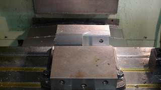
So here we start with a couple of pieces of stock and a chunk of aluminum for the 2nd operation fixture:
Stock clamped for the first operation:
And the first operation complete:
The radial grooves were done using a 1/4" diameter end mill with a ball end and plunging in the Z direction while doing a G3 arc move. I used a .250" end mill but used 6mm (.236") balls to have a little clearance so that they no not bind due to the unavoidable manufacturing tolerances.
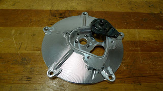
Now I made a fixture plate that this part could bolt to and ran the 2nd operation program:
I ran a 2nd part to have a spare. After welding the radial bearing boss on and a little manual machining for the cable end pocket and retaining pin and the part was finished.
You can see the rotary/linear action in this short video:
That's one more subsystem complete, next will be some internal shafting for the oil pump. these are simple parts so will be done manually on my Hardinge lathe and should be done in a day or 2.


