Saturday, February 12, 2011

Kolb Comes Through

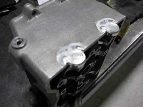
Many thanks to Scott Kolb of Kolb Machine for delivering 2 perfectly capped and smoothed cylinder heads.  Scott is a fabrication ace and it is him who I turn to when my ham-fisted hand work simply will not be up to snuff.  He is also an accomplished builder in his own right, having several land speed records under his belt and several more in his sights.  His blog site shows a lot of cool stuff on his LSR project.  There is also some great footage from his visit to the A2 wind tunnel in North Carolina, the heart of NASCAR territory.  The visit was very productive and informative for both learning about his existing partial streamliner and doing tests on shapes for his future 200+mph 125cc full streamliner.  It was my first wind tunnel test and hopefully not my last.

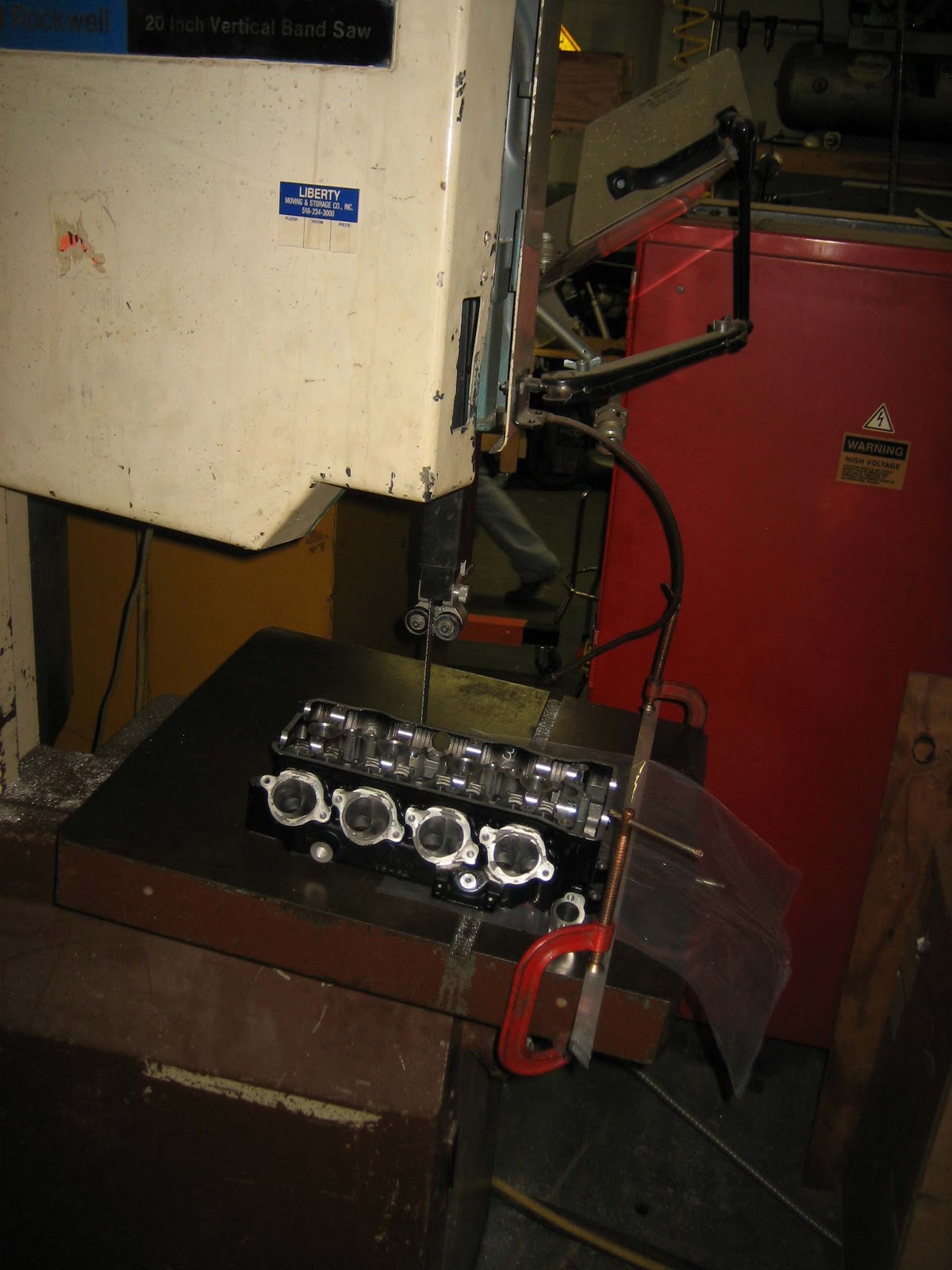
I had 2 sets of ported heads and kit cams purchased from Attack Kawasaki from one of their last Formula Xtreme bikes when that series still allowed significant engine modifications.  These heads were sectioned on a bandsaw and cleaned up on the mill to leave the camchain tunnel and adjacent 2 cylinders.

Bandsaw cutting:

Cleaning up surface on mill with face mill:

I then stripped the paint off the parts and shipped them up to Scott.  He proceeded on the 2 step process first documented in an earlier post, Head Weld Test.  The 2 piece cap is to insure the internal separation from the oil and cooling passages remains separated.

Cutting out the cap plates:


Top cap plate unwelded/welded:


We installed extra valves and springs during the process to ensure the valve seats did not slide out of position due to the high heat input during TIG welding.

Fully welded part:

We decided to also fill in the cam bore 1/2 circular cutouts to make the gasket surface a single plane to allow using a waterjet cut Cometic gasket

Filling in cam journal external bosses:

Fully welded:

Trimmed: 

Scott then ground out all the welds giving the part a very clean and manufactured look.


From here I will remove the valves/springs and mount the head on our trunnion fixture to clean up the gasket mounting surface.  Some custom gaskets are on the way from Cometic to keep all the oil inside and we're a few steps closer to having a complete engine.

Until next time...


Thursday, February 10, 2011

Machining the Crankshaft Connecting Rod Journals

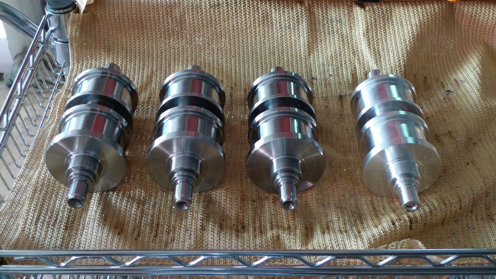
I was able to get some more time in on Peter's mill and got the journal machining done on all 3 crankshafts. After the last step the cranks were turned but did not have the offset journals machined, as shown in the following picture:


This step moved the parts from the lathe to the mill.  I hold the right side of the crank in a 3J collet and supported the outboard side with a tailstock with a dead center.  The setup is shown in the following picture:


The process is the same as the aluminum test part, except the spindle speed and feeds were much slower, the depth of cut was less, and I used a roughing and finishing end mill.  The finishing end mill was custom ground to have a flat end which minimized the uneven surface that the test part ended up with.
The roughing end mill has a serrated cutting surface and provides an aggressive edge to remove large amounts of material, allowing the finish end mill to only remove the last .02", last longer, and hold tighter tolerances.  The end mills were purchased from Mari Tool and held in a 3/4 milling chuck for maximum rigidity.

Now on to some cutting shots.  First roughing in a step pattern produces a square journal:


Once both journals are roughed out leaving a square the next operation employs a 4th axis move to create the rounded thrust and journal surfaces:

Here's a couple of videos showing the finishing passes for both the thrust and journal surfaces:
       
and
       
The resulting surface finish and accuracy were excellent.  Here's a quick spin of the final part.
       
The great part about CNC is now I ran the same program 2 more times and ended up with 3 great parts.

Next steps for the crankshaft are to machine the camchain sprocket teeth and drill the oil holes.  Hopefully i'l get to those operations next week and be ready to ship them out for gear hobbing and plasma nitriding shortly after.

That's all for now.

Monday, February 7, 2011

And now for something completely different

After working on all these engine parts I got a bug to shift focus and to make some inroads on the pile of chassis parts that need to be made.  My first choice was to make the upright legs for the front suspension.  These legs are central to the variable flex idea that is incorporated in the front suspension.  Instead of following the current ideas on overall bike flexibility which uses stiff telescopic forks and a slightly flexible chassis, I prefer to have the flex where it is needed-at the wheel.  Telescopic fork equipped bikes don't have much of an option here- the forks needs to be relatively rigid, otherwise they would bind up when flexing under braking load, preventing smooth suspension movement.  With the linkage suspension I am using it is possible to have a very stiff chassis and a-arm structure to allow smooth suspension action and accurate wheel location yet have flex built into the upright legs to accommodate small bumps and irregularities in the surface when leaned far over.

From the years spent campaigning my single cylinder racer I have a good idea of the directional stiffness that will produce good results.  No, I won't go into specifics here on what the stiffness ratios are.  As expected, maximum stiffness is needed in the braking direction and much less needed in the transverse direction.  The initial uprights I designed worked well, but was a bit complex to make quick copies of.  I then moved on to a much simpler design using rectangular steel, some with welded on stiffening plates to tweak the stiffness as testing dictated.  The latest version of the front suspension uses some old and some new to result in a low friction assembly with easily characterized controlled flex characteristics.


First upright design using suspended headstock design:

This design worked very nicely but was a bit complex to make variations on.  The suspended headstock and all ball bearing upright mounts provided smooth action and good feel but at a weight penalty to later, simpler designs.

Second design style using spherical bearings (bearings not shown):
This design had the benefit of being easy to replicate with subtle stiffness variations but I found the spherical rod end bearings reduced feel and required frequent replacement in order to maintain optimum performance.


Final version for the V4 project bike:
This version separates the parts into a bearing carrier and legs that bolt on.  It enables easy modifications to the stiffness by making new leg parts with varying dimensions yet keeps the bearing mount arrangement stiff.  The weight is in between the first two designs, a good overall compromise in my opinion.  The upright legs will be machined today.

As with most billet parts I started with a large plate that both parts could fit in.  I bolted this directly to the CNC table and machined the mounting pads and axle holes as shown in the following image:

I then machined a fixture baseplate that would locate on these premachined features and allow me to complete the part:


The fixture locates on the machine table with dowel pins allowing easy and accurate setup for making more parts.


I then cut out the individual parts leaving extra stock around the perimeter and bolted them to the fixture plate as shown:


Next came the pocketing and chamfer operations:

Resulting in a sweet looking part:


Mirroring the toolpaths allowed me to create the 2nd part with a minimum of hassle resulting in a very stiff looking assembly:  This design also makes use of the latest radial mount Brembo billet calipers for the ultimate in progressive braking feel.


I don't mention it often enough so a big thank you goes out my shopmate to Peter H. for allowing me essentially unlimited use of his 4 axis CNC mill.  Without access to his machine I'd be making much lower quality parts on my old BP 3 axis relic.  And I'd still be figuring out how to fit the engine castings on it!

In the next few days I hope to move on to the upright bearing housing and handlebar mount, both of which need the 4th axis and trunnion table.

Until then.....
Wednesday, February 2, 2011

Initial Assembly testing


After the rush of the holidays and new year I was able to get more time in on the engine.  I did some long block assembly tests to check fit of all the reciprocating parts. All the parts fit properly and go up and down as the crank goes round and round.

Main bearing/conrod journal assembly


The 180 degree crankshaft was chosen to minimize the fluctuations in reflected crankshaft inertia torque.  This is similar to the idea used in Yamaha's M1 GP bike and R1 street bike.  Normal I4s have a flat crank which means that when the outer 2 pistons are at TDC the inner 2 pistons are at BDC.  This results in the reflected torque of the entire piston/conrod assembly varying greatly.  At high engine speeds variation can be up to 20 times the combustion torque.  Because this variation is both positive and negative this variation of course does not add to the engine's output torque. What is does do is overlay a large amplitude noise signal over the small amplitude torque signal, muddying the rider's connection between the throttle and rear tire.  This Youtube video from Yamaha does a good job explaining the difference in the 2 configurations.  At around 2:30 the details of the inertia torque variations are explained.  Yamaha's Furusawa wrote a technical paper analyzing the signal to noise ration of various crank configurations which backs this up.

Where I am departing from the status quo is my choice for a screamer firing order.  I am proposing that the minimized crankshaft inertia torque variations is the real reason that Ducati twins seem so much more driveable than the other I4s in WSB.  Single crankpin vee twins by default have a much better crank inertia situation than the normal I4 because of the piston/cylinder bank angle relationship.  I think the whole 'big bang' theory is rubbish and therefore am trying to get the best of both worlds- low crank torque inertia variation for improved driveability but a screamer firing order for maximum power potential.  There is a small penalty of having to add counterweights to the crank to reduce the rocking moment produced by the 180 degree crank arrangement but I think the benefits will far outweigh the costs.

You can see the details of this in the following 2 pictures:

The front bank cylinders are at TDC and BDC while................


The rear bank cylinders are both at midstroke.   This configuration results in a minimal variation in crank inertial torque and I hope a clean signal from the rider's wrist to the crank.

You can see the interplay of the pistons in this short video:


Next up is checking out the camchain runs and doing a longblock assembly test with the cylinder heads and cams.  Once this is done I can send both crankcase top parts to Millennium Technologies for nikasil plating and final honing.  While the parts are being plated and honed I have plenty of smaller parts to make, various shafts and both engine side covers.

That's all for now.

Wednesday, December 8, 2010

Crankshaft Offset Journal Test Part Machining


We left off on the crankshafts with all the lathe operations being complete and all 4 parts being ready for the 4 axis mill work.

The next operation is to do the offset machining needed for the connecting rod journals.  There are two techniques available: eccentrically mount the crankshaft in a special chuck on the connecting rod axis and turn the journal or mount the crankshaft on the main journals and eccentrically turn the conrod journal.  The first option is easier to program but more difficult to fixture, is very unbalanced during machining, and requires part repositioning for each conrod throw.  The 2nd option is more complicated from a programming perspective but is easier to fixture, is balanced, and needs no part repositioning.  I chose the 2nd option as once the upfront programming work is done making multiples is easy and repeatable.

Due to the low cutting forces due to the aluminum test part material and a desire to get a sample part machined I opted to leave the outboard 4th axis support off.  Machine time these days is limited and getting a sample part quickly was of prime importance.

The mill setup is as shown:

The first operations are simple pocketing to remove the majority of the material in the most efficient machining technique.  Pocketing was done at increments of 90 degrees and ended up with squarish journals.


Here's a short movie of the squared off journals:


Once this stage was complete I moved on to the 2nd program which created the fully round journals.  The video of this move is subtle but cool.  The machine is performing a G3 arc in the YZ plane (G19) while the 4th axis is doing a rotary move from 0 to 360 degrees.  The result is an eccentric true cylindrical surface with none of the approximation concerns usually associated with surface machining type toolpaths.


This is the first journal after its finishing pass.


And this is a short movie of both journals.

The 3 slight ridges on each journal are an artifact of the dished end of the end mill used for the test cut.  For the final steel parts I had a 4 flute finishing end mill specially modified to flatten the end face and keep it center cutting.  It is not suitable for machining aluminum so in the interest of quickly getting a verified program I used a mill with standard aluminum cutting end geometry.

This part is being sent to a grinding house for finishing of the journals so the absolute tolerance and surface finish are not as crucial as long as there is enough stock left to clean up during grinding.  After consulting with the grinder I am leaving .010" of stock on the main journals and .020" on the connecting rod journals as grinding allowance.

Now that I have a sample crankshaft we can test assemble a short block with the major rotating components: crank, conrods, pistons, and also trans and oil pump/drive components.  Once we reach that stage there will be lots of pictures!

That's all for now.

Chris

Tuesday, December 7, 2010

Machining the Torque Plate

I was able to get at Peter's mill for a bit last night and did the machining on the torque plate.  This part is used during the final cylinder honing process to simulate the distortion of the bore caused by the cylinder head bolt forces.  It is useless to create a perfectly circular bore if you are then going to distort it with clamping forces. This procedure creates a more accurate simulation of real world use during the bore process that results in an out of round cylinder when unclamped that shifts to round as it is clamped.  I've heard that extreme tech engines like F1 do the honing process with a torque plate while the block is heated with hot water to even more closely replicate actual operating conditions.  I'll have to see what MT thinks about this one!


The part started with a piece of 1" thick 304 stainless steel plate that was waterjet to a rough profile by North Eastern Water Jet.  Andre of NEWJ is always very helpful in suggesting material they already have in stock to shorten lead time and reduce cost.  The cost of the waterjet cut blank from NEWJ was less than a comparable piece of stock from the local supply house and saved me from having to hog out the majority of the cylinder bore.
The machining of the bores and screw/dowel holes was uneventful.  The part is now nearly finished.  The last issue is that the mill finish on the top of the material is not fine enough to clamp on the head surface without marring the aluminum casting.  To fix this the part needs to be surface ground to a 8 microinch finish.  I'll bring the part to a local vendor, Garden State Precision, who has the equipment and expertise necessary to do the job properly.   I'll drop it off in a day or 2 and since this is not a rush pick it up in a week or 2.


While I am at GSP they will also do another small grinding job, thinning the crescent-shaped crankshaft thrust bearings.
The crank bearings are from a ZX10R.  The journal bearings are to be used unmodified but the thrust bearing is slightly too thick to fit into my crank design.  Instead of having a full-on special made, which is expensive and time consuming, I will have these stock bearings ground from the backside to the appropriate thickness.  Inexpensive and just as effective.  I'll have them grind matched sets in .0005 increments to allow me to dial in the desired crankshaft end float.

Coming up is the crankshaft rod journal machining.  Hopefully in a few days but you know how it goes!


Until next time,
Chris

Monday, November 22, 2010

It's déjà vu all over again


Seems like we were here a couple of months ago!
 
Once all the programming and fixturing is done making multiples is fast!  That's the beauty of sand casting and CNC.  Minimal material removal yet still a complex multifunctional part for a reasonable cost.  The first operation on the 3 new parts ran smoothly.  The crankshaft blanks nests nicely in the journal area.

Now I have to tear down the mill setup and reinstall the trunnion, dial it in, and run the remaining 4 axis programs.  If those run with no problems the two upper crankcase parts will be sent off to Millennium Plating for NSC plating and honing.  I'll send the J&E pistons with the castings so that Millennium can mic the actual pistons and get the piston to wall clearance dead accurate.

One task before plating is to finish machine and surface grind the stainless steel torque plate.  This will be bolted to each individual cylinder bank to simulate the head clamping forces during the final honing process.


When an engine is final assembled and you tighten the head bolts the cylinder walls distort slightly from round.  This is bad for piston ring seal so a the use of a torque plate simulates the distortion of clamping so that the cylinder wall is honed to a round shape in a condition close to actual running conditions.

That's all for now.  Hopefully I'll have the balance of the machining done sometime this week.