Tuesday, October 18, 2011

Helical Clutch Actuator

This post will document the fabrication of the mechanism that converts the linear pull of the clutch cable to the motion required to release the clutch.

As this is one of the user interface elements of the bike some attention needs to be paid to the forces and leverages involved to be sure the clutch pull is not too stiff yet firm enough to allow the rider to modulate it a bit.  This was pretty simple and I found a reduction ration of about 5:1, meaning that .5" of clutch cable pull should equate to .1" of movement of the clutch pressure plate.

Now that the desired leverage ratio was determined I needed to design a mechanism that fit the available physical space.  As the clutch is protruding slightly past the frame on the right side of the bike I wanted to keep a low profile so that the actuator was not the first victim of a lowside crash.  Several of the current Supersport bikes use a rack and pinion style actuator with the clutch cable tied to the pinion and the rack having a thrust bearing to mate with the pressure plate.  This style is nice but is long.  Being long does not matter for the I4 engine style as the outer cylinder is wider than the clutch/trans area but the extra length would not package well in my V4 configuration.  I thought about using the self contained helical actuator from a SV650 as done with the custom slipper clutch for the Rotax single:


This design worked well but was a little long and visually messy as there were several external components that were not that pretty.  It also was a bit difficult to properly seal and since oil on the rider's left boot is not a good thing I set this idea aside.

Knowing that I'd like to have about .15" of pressure plate travel (a bit extra is always nice to allow tuning of the slipper effect) I set about designing a thin actuator that provided the needed travels.  I ended up with a very slim design that used roller bearings for all motions involved to minimize friction and maximize feel.  One important design point was that I wanted to use a readily available clutch cable so spares were easily sourced and inexpensive.  Since there are some Kawasaki OEM parts in the engine it ade sense to design around a Kawasaki ZX6R cable which is what I did.


The aluminum housing parts are already made so the helical actuator part is the only one left.


In this cross section through the clutch shaft you can see the details.  the release balls are not visible but there are 3 of them in 3 matching helical grooves.  As the clutch cable (shown in the first CAD rendering above) pulls on the grey part it pivots around the radial bearing while the release balls ride up in their grooves, thereby moving the grey helical actuator away from the engine.  The gold connector rod then pulls the clutch pressure plate up with a thrust bearing sandwiched in between to allow rotation of the clutch.

You can see them and the helical grooves in both parts in the following image:

 The design met its 2 primary goals well: a. slim design that needs less than .6"of thickness from the outside of the clutch pressure plate, and b. Smooth motion through the use of roller bearings on all motion axes.  Now its time to machine.

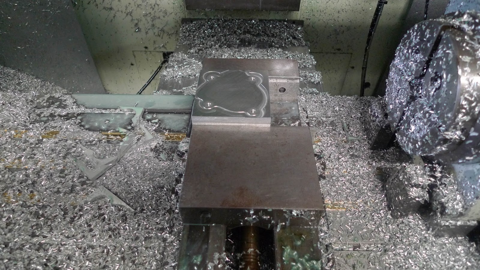
So here we start with a couple of pieces of stock and a chunk of aluminum for the 2nd operation fixture:


Stock clamped for the first operation:
And the first operation complete:

The radial grooves were done using a 1/4" diameter end mill with a ball end and plunging in the Z direction while doing a G3 arc move.  I used a .250" end mill but used 6mm (.236") balls to have a little clearance so that they no not bind due to the unavoidable manufacturing tolerances.

Now I made a fixture plate that this part could bolt to and ran the 2nd operation program:


I ran a 2nd part to have a spare.  After welding the radial bearing boss on and a  little manual machining for the cable end pocket and retaining pin and the part was finished.

You can see the rotary/linear action in this short video:

That's one more subsystem complete, next will be some internal shafting for the oil pump.  these are simple parts so will be done manually on my Hardinge lathe and should be done in a day or 2.

Monday, October 3, 2011

Let's get things moving!

Here's you chance to help us out!  I've been moving along with the project as I can but progress can be much faster with your contribution.  I want to try to get the engine running by the end of the January and we can get there but need your help.  I've set up a PayPal address that will accept donations of any amount.  You can click the button here or the donations button on the right side of the blog under the followers.


What I need is $25,000 to get the first 2 engines up and running.  The money will be spent on the following items:

-3 of more sets of crankcase castings  $3000

-finishing of 3 crankshafts: $4000

-primary drive gear grinding for 3 pieces: $1200

-Nikasil cylinder plating for 4 castings: $2200

-ECU/support electronics: $10,000

-dyno engine fixture: $2000


There's a little cushion in there for potential bumps in the road.  These expenses are for outside vendor work and components.  If I could I'd make this stuff in-house but in these specific areas it is best to go to the acknowledged experts in the field to get the work done right.

Donations of any amount are accepted.  For a $50 donation you will receive a t-shirt and sticker.  $250 gets your name on the fairing in 24 point type.  Donations of $500 will earn an engraved name on the cases of the first and second running engine.  Imagine how cool it will be to show up at a racetrack and be able to point out your name engraved on a racebike engine!  I have not though about perks for gifts over $500 but feel free to test my imagination!

Regardless of how much comes in through these donations I am still moving forward as fast as possible with the project.  I am currently throwing everything I have at it and will continue to do so.

Thanks for reading and following the project, your comments and readership help me to continue pushing for completion.

Saturday, September 17, 2011

Another operation done....

To keep the streak going I finished the clutch cap on the lathe today.  The first milling operation went smoothly but this lathe operation had a slight bump or two in my way.  I initially programmed the part using conventional tooling but the recessed pocket really needed some more specialized face turning cutting inserts.  The problem was minor and did not cause any undue headaches but the program needed to be redone.

The first step was to cut some profiled soft jaws to hold the part:
The small burrs you see are away from the profile and will not cause any clamping problems.


Unfortunately I was on such a roll I machined all 3 parts without taking any pictures of the process!  Here's the final 3 pieces looking really good:

The clutch side is nearly complete and looking great.  I'll try to get to the oil fill and crank end plugs today then next week I have to do a bunch of contract machining so will likely be too busy to make bike parts.  Damn.  I will try to get to something done to keep the streak going.

Friday, September 16, 2011

Gettin on a roll

Ahh, peace and quiet to make bike parts.  As close to nirvana as I can get these days.

Today was a low hanging fruit, the clutch cable actuator cover.  This is a cute little piece with the gear to wing logo and 2 versions of the name, "Cosomoto' and 'Cosentino'.  I'm partial to Cosentino for obvious reasons but Cosomoto is just to close to Quasimodo.  Either one, I'm covered!

Parts blanks and layout sheets:

Simple fixture plate:


Op 1 (top) and 2 (bottom):

2 pairs:

With the top surface finished out:


Next I'm going to finish up the clutch cap and machine the helical actuator and that will then let me assemble and test the clutch actuation mechanism.

It's great to see the visible progress.  A running engine can't be far away.

Thursday, September 15, 2011

Our 5 min of fame just went by.....

As I mentioned in a previous post we had the guys from the Discovery Channel HD Theater over here shooting some footage for an upcoming episode.  It turns out that upcoming episode just came up!

They are broadcasting it this week on the Discovery HD Theater channel.  Its the show 'Cafe Racer'.  Its Time Warner channel 767 in NYC.  It's the episode with the description 'A junkyard chopper cradles a hidden gem; defense contractors tackle cafĂ© racers; and a NY artist tries to exercise some two-stroke demons.' I'm not quite sure which one of those describes us but check it out, it should be on multiple times each day for a week or so.

They took a lot of footage for a couple of different episodes and since we have not seen it yet I'm not sure what part you'll see.  I do hope it presents us in a somewhat decent light!  Let me know what you think.

One more time

Wow, nothing like a lack of paid work to allow me to get more done on the bike!  Seeing that the clutch side is getting closer to completion I started on the clutch cap, the cover that also houses the helical clutch actuation mechanism.  On race bikes it is crucial to be able to change the clutch plates easily so I did as many racebikes do and made the clutch cover 2 pieces:  one main housing and one small cap that covers the friction plate area.

I had a rectangular block of aluminum that was plenty for 2 parts but just too small (I thought) to get 3 parts out of.  After a bit of creative nesting I was able to make 3 blanks with parallel sides for easy clamping.
This part is different from nearly all the other machined parts on the bike in that it has a domed surface and curved stiffening ribs:
This makes machining more time consuming in that I have to sweep an end mill along the surface with a very small stepover.  The end result is a light and strong part that also looks pretty cool because of the slightly visible tooling marks.

The process starts with a large stepover (producing pronounced scalloping due to the use of a ball nose end mill) and as the remaining material decreases the software reduces the stepoveruntil the remaining scalloping is at an acceptable level.

Large stepovers on roughing passes:
Gradually getting smaller:


Small stepovers on final finish passes:


The center area of the part is where the helical clutch actuator will be.  The 3 small arc shaped cuts are helical paths that will have a stainless steel ball installed in. A pivoting plate with mirror image grooves will mate with it and when the plate is pivoted by the clutch cable the balls will ride up in the grooves and pull the outer clutch pressure plate away from the friction discs, thereby releasing the clutch.  It's not exactly easy to explain but does work.

I was able to get 3 useable parts from the single block of aluminum, one with a weird surface finish due to improper software settings in the finish machine operation.  It does not affect the part's function and can easily be remachined once the back surface with location features is done.

This part is also unusual in that it will require one mill and one lathe operation instead of 2 mill operations.  The outside of the part is suitable for milling but the inside of the part is a simple revolved surface, making the lathe the appropriate machine to use.  I have a bunch of lathe work to do next week but can hopefully sneak this part in over the weekend.

See you soon.

Monday, September 12, 2011

Finishing the clutch cover

What a productive week for the bike!  I was able to get some more time in on the mill and complete the machining of the clutch cover.  The last operation on the part was machining the interior pockets, profile, and starter gear mounting features.

The next step is to make a fixture plate that can locate from these previously machined features then bolt the part to it and finish the outer surfaces.

First, I machined a plate with some dowel pins to accurately locate in the machine table t-slots:

Then I ran a second program that drilled a hole pattern to match the mounting and alignment holes of the part:
I then bolted the part to the top of the fixture plate using the expendable bolt holes made in the first operation:

Holding it like this will allow me to run the first half of the program, pause it, reclamp the part using the perimeter mounting holes and remove the large fixture bolts, then resume the program and complete the part:


Notice how the large circular part left in the previous operation has now dropped out off the final part.

Repeat those steps and I ended up with 2 good parts:
I bead blasted one to see how it would look and while the part looks better once you assemble it next to the crankcase cast surfaces the billet one seems more appropriate.


The blasted one is too close to the cast surface finish without being the same.  Cool, but I like the billet.  Maybe I'll have the blasted one color anodized once we get a better idea of the overall color scheme of the first bike.

Next part is the clutch cap that bolts to the outer large circular boss and contains the helical clutch release mechanism.  Hopefully this week will have some time for me to get to it.

After bolting this part on I'm realizing that we're not too far from a complete engine!  Wow.  Time to knuckle down and make it happen ASAP.