Friday, April 6, 2012

Back in action, now with T-shirts

Well, that was an extended absence.  It was not too bad from my perspective since I was working on a motorcycle-related project.  Now that the first stage of the TZ250 engine case project is done so I can get some time to get some of my bike project in.  I'm sure my control arm material stock and programs are feeling neglected, but hey, that's life.

One point of good news is that the T-shirts have finally come in.  I ended up using Metro Printing & Promotions because of their good turnaround and great pricing.  Steve was a big help in getting the graphics sized and located properly.  In keeping with the Made in USA theme of the project I aptly chose American Apparel t-shirts.


The shirts look great (apart form the wrinkles) and are super comfortable.  Thanks again to Sacha Halenda at Form Five for the clean and elegant layout.  I'll be sending out the first batch of shirts next week so all those who so generously gave to the cause can expect something in the mail soon.  If anyone else is interested I have plenty of extras ready to ship.  All donations are appreciated.

Finally, next week is a bike part week.  I'll be definitely machining the upper control arm and hopefully getting the lower control arm done too.  Posts and pics will follow.

That's all for now.

Chris

Saturday, February 18, 2012

Finally, someone hired me to make racebike parts!

For the past couple of months I've not had much time at all to devote to the bike project.  Besides the usually unproductive weeks around the holiday season I had to do some rebuilding of the CNC mill's 4th axis after discovering an extremely worn worm wheel.

After the rebuild the 4th worked better than ever, which was great timing as I had a major machining project to do.  And it was for a racebike!

Here in the US there are still a few diehard 250 GP guys.  I can't blame them as a 250GP bike is the ultimate expression of economy of design second only to a 125 GP bike.  One of these guys is Bruce Lind.  He still runs them and runs them fast out there on the West Coast.  Unfortunately, Yamaha's supply of crankcases is becoming limited, and combined with the flaw of receding bearing inserts, led him to try to have them converted to a billet design and do a short production run.  With the cast cases failing after less than 2 seasons of use if a billet version could be made to last longer it would be worth a slight price premium.  After a false start with a 2 stroke vendor used to parallel twins Bruce managed to find me through the USGPRU messaging boards.  The USGPRU is the sanctioning body for FIM 125 and 250 GP racing here in the USA.  They are doing a great job of integrating the new 4 strokes into the program while allowing people to continue running their 2 stroke bikes.  Under the Team Incomplete banner I had a couple of very fun seasons running parts of their schedule on my RS125.

Its funny how these things work out.  The only reason Bruce found me was that I was making an engine for the class that obsoleted his favorite machine!  Anyway, Bruce saw the progress of the V4 project and decided it was worth a try to move the project over to me.  After some brief discussions we agreed to terms and I started reverse engineering the cases.  They are some pretty complex parts and I knew from the beginning that doing a straight copy would be extremely problematic due to the complexity of a part cast using internal cores.


Bruce also wanted to take advantage of the redesign to incorporate the latest porting and stuffing specifications.  Unlike a 4 stroke engine with cams and valves that usually removes material when porting, a 2 stroke porter adds material to the inside of the crankcases to smooth flow between the reed cage and the transfer ports and to alter the compression that occurs in the cases.  These cases were modified by a factory Yamaha race team so had a highly desirable and effective configuration.

The reverse engineering was more a redesign process using the same shaft and bore centers than a strict copy.  In order to be able to machine the parts in a reasonable amount of time I had to convert a lot of the smooth cast surfaces into a faceted version that could be milled accurately and quickly.

Since we would be starting with quite large blocks of aluminum I also needed to find the most economical way to mill aluminum.  Solid carbide end mills, while rigid and capable of high metal removal rates, tend to dull and wear out after a time and then the entire tool needs to be replaced, a wasteful process for such a premium material..

An alternative tool style is to use small carbide inserts mounted to a steel body.  This style of Cutter allows you to quickly replace the dulled cutting edges with replacements at a minimal cost.  A bit of online research led me to a Koroloy insert mill from Curtis Tool.  Curtis was a big help in finding the right insert style for the part/machine combination and an extended toolholder for the deep pockets.  These are pretty mean looking big carbide inserts that cut aluminum like the proverbial hot knife through butter.

I purchased 2 versions, a short 2" diameter version for the majority of the roughing, and a 1 1/2" version on a long extension for the deep gearbox pocketing.
Even with 6" of projection the cutters worked great with no chatter.

Here's a couple of shots of the assembly so far.  The upper part is complete and the lower part is mostly complete.  Once the final outer pocketing is done the parts will be assembled and then all the bearing bores finish machined as a matched pair.


The top part was made from a medium size billet that I bolted directly to the trunnion table:


After a whole lot of machining the resulting part emerged:


The lower part was made from an obscenely large chunk of aluminum.  It was so tall I had to manually load tools because of clearance issues!

The final version of this part will weight less than 10% of the original billet weight.  Most of the internal and detail work is done, all that is needed to finish is the external clearance routines then final boring.


These parts are by far the most complex billet pieces I've made so far.  My V4 engine castings were of a similar complexity level but since they were castings there only was a relatively small amount of actual metal removal and the multiple part orientations were relatively easy to relate to each other.  These pieces started out as a giant block and evolved though various orientations and machining operations.  The enormous amount of metal removed made both the machine time much longer and that much harder to visualize.  I was glad to get this far with no errors or machine crashes!  I have a much greater respect for sculptures after doing this project.

If you still run a 250GP bike and need a new set of cases please contact Bruce and order up a set.   The same goes for anyone that wants the coolest set of bookends ever.  I'm almost done with the first set after which Bruce will assemble and test them.  Once any final tweaks are integrated into the machining programs we'll go into production.

On the other hand, if you have a part or engine or entire bike that you'd like to reproduce, give me a call and we can work something out.

Once this set is finished I will get back on track and resume machining bike parts starting with the upper control arm.  Hopefully that will happen next week.

Chris
Thursday, February 16, 2012

Back from the void

I've been a bit busy on a cool project the past couple of months, something worthy of a post on this blog.  Tomorrow I'll post some pics of the most complex billet parts I've made so far.  And they are for a racing motorcycle.


Chris

Thursday, November 17, 2011

Finishing the steering stem

It was way back in July that I turned the blanks for various length steering stems.  The various lengths allow me to adjust the amount of dive that happens under braking.

Here's where we left these parts:

Now these parts will be brought to the 4 axis mill and have the pivot holes and clamping faces machined.  then i'll switch to another setup and trim and chamfer the ends.

The first step is holding the parts in a 3J collet on one end and with a dead center in the other to ensure the part axis is coincident with the mill 4th axis.  That means that the zeroth step is to align the dead center to the 4th axis.  I machined a round adapter that helps greatly in this process:
I then remove this mandrel, reinstall the dead center quill and then clamp a part:
To check the alignment I held a .0001" indicator in the mill spindle and rotated the 4th axis.  the part was within .0003 TIR, which is an excellent runout for a 2nd operation clamping.
Now that the part is properly clamped and in alignment I can machine the features that mount the upper and lower control arms.  the machining is 4 pocketing routines and 2 reamed hole routines ending with the almost complete part:
Repeat this a few times with appropriate modifications for the various lengths and i have a bunch of useable parts:
Now there is a simple cleanup operation to do on each side to round and smooth the ends.  The part is held in the 4th axis in a 3J collet with the end just sticking out.
I profile the end, then chamfer it and repeat for both ends top and bottom:
The finished parts are pretty sweet lookin:
 Especially when assembled in the spider:
That's one more part to cross of the to-do list.  The front end is starting to take shape, i'm only missing the control arms which are next on the list of complex parts to do.  I may try to squeeze in a few simple parts before that, let's see what the next week or 2 bring.


That's all for now.

Monday, November 14, 2011

Front end assembly

Now that the spider machining is done I can bolt the legs on and hope the axle holes line up!
As expected both legs fit properly and the axle is a nice smooth sliding fit through both legs.  The assembly looks pretty cool, especially compared to the simple previous design.
Once I finalize the rim/brake rotor combination the radial caliper mounting holes can be machined in their proper places.  The calipers are the dual Brembo radial mount big pad CNC versions (with the radial caliper too) which will be total overkill for such a light bike, but we like overkill on the brakes, which should be the bike's strongest point.  Why Brembo?  They are the best.  Period. I got them from Fred Renz at Yoyodyne who has a huge selection of high end parts at good prices.  Rims, brakes, bodywork, slipper clutches, etc.  No waiting for drop shipping from the manufacturer, he's got it all in stock.

The rotors are Brake Tech Iron Rotors that use a different method than the usual round button to transmit the braking torque from the rotor blade to the carrier.  When we were running the Ducati/Rotax single which only had one front disc the buttons on various name brand rotors were constantly being galled and requiring replacement. Once I switched to the Brake Tech rotors all wear was eliminated.
In this photo you can see the flat surfaces that transfer the load.  The buttons are merely for axial retention.  All the parts are finished to a high level of detail with a nice even anodized finish.  The rotors are even cryo treated!

They are definitely a manufacturer I recommend when replacing brake rotors.  If you have deeper pockets they also make a ceramic matrix composite rotor that works great on the street.  It is super light and great for a track day bike but unfortunately not allowed by most race organizations.


Next post will be the 4th axis work on the steering stem, hopefully in a day or 2.

Monday, November 7, 2011

T-shirt design is in!!

After starting a donations post for the blog that you can see here I realized that we didn't have any t-shirts available and didn't think people would want a plain fruit of the loom.

My solution was easy, call Sacha Halenda of Form Five and have him whip up something superb.  Sacha is responsible for creating both the Cosentino Engineering logo and the 'Cosomoto' name and gear/wing logo, among many others.  He has a great talent for creating an identity that is new and unique yet still allow that graphic to evoke the familiar emotions that consumers need to relate to a new entity.

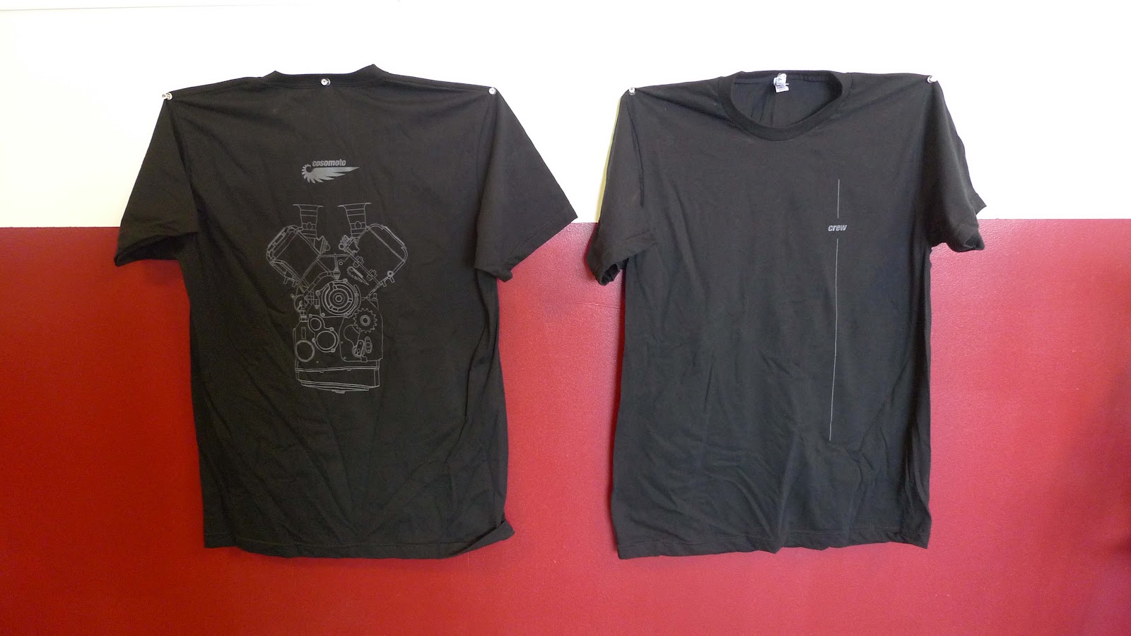
The first shirt design focuses on the V4 engine design and features a large wireframe drawing of the motor on the back side and the text 'crew' on the front with some stylish accents.  Although we have not finalized which vendor will print the shirts we will be using shirts that are 100% Made in the USA.

Front:


Back:
 
The bonus of having one of these shirts is that if you are wearing one at a race event we're at you are welcome to come in our pits, pull up a chair and make yourself at home.  Without one of these tees you can come in but you'd better not pull up a chair.....  Also, you'd better like Mexican food as we have a rule about not eating anything else for dinner during an event.  We have a detailed map of every Mexican restaurant (or taco truck in the case of the Bonneville Salt Flats) within 50 miles of every US racetrack so are never caught unprepared.  Cue whatever jokes you can think of about more gas to help the bike go but it works for us!

As we continue with the project and as interest allows I'll have Sacha make more shirt designs relevant to our current state of progress.


If you like the shirts please go over to the donations page and make a contribution.  Don't forget to let me know what size to send.


Chris

Machining the front spider

With momentum still rolling along I started on machining the center spider for the front suspension.  This is a multifunctional part that holds the upright legs, defines the steering axis, and connects to the control arms and steering links.


We'll move along the well-rehearsed path of machine fixture, mount part, machine part, reorient, machine part again.  The fixture has several dowel pins to register the part in correct alignment before it is clamped down onto the swivel pads that provide proper spacing and restraint.


Here's the part clamped in place:


I then machine the part in 3 steps in this arrangement: the top and 2 sides.


These first 3 operations are all done with simple end mills and drills.  When I index the fixture 90 degrees to machine the steering stem bearing seats we will need to use some extended reach tooling.
Here's the 2 flute insert mill used for roughing, the boring bar used for finishing, and the custom long reach retaining ring groove tool made from a slim carbide slitting saw and some precision ground 5/8" diameter shafting.
Here's the finished bore:
And some finished parts:


There are 2 different versions of the part, a tall one that provides much less front end brake dive than telescopic forks and short one that provides closer behavior to teles.

Once I do some deburring and test fitting I'll post some images of the front upright assembly.  It will look really cool.

That's all for now.