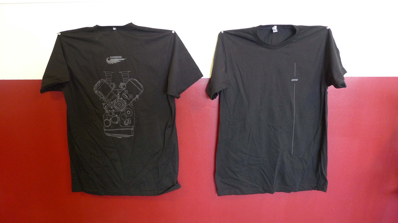
Here's a little update on the fundraising front. T-shirts have been going out to the twenty or so people who generously contributed at that level.
I've also had one taker of the $250 level for fairing display and that was Chris Hodgson from San Jose BMW. I've known of Chris since his days with CC products, having been exposed to the rare BMW motorcycle racing bug through Gregor's Boxer project. The engine was stuffed full of CC goodies. I also met Chris a couple of years ago when he pitted next to Scott's LSR bike at Bonneville. I had some of the V4 engine parts with me to show at the AHRMA Miller round and he was like 'Hey, I follow that project online!'. It was a rare moment of the student becoming the master, or something like that. Anyway, Chris dug deep and helped out. Thanks!
Over the weekend I had the first $500 donor to have his logo engraved on the engine cases. The person was Lawrence Smith, an Aussie that not only loves performance bikes, and not only knows machining and engineering, but is a FFE (funny front end, an industry term...) advocate! Amazing! How do you know he is a FFE lover you ask? Well, this is his first project bike:
Pretty damn cool looking IMO. There's a nice writeup with some pics and video over at TheKneeSlider. Lawrence is very happy with how the bike performs and in his own words 'after all FFE is the future'
He sent me some pictures of his next project that just got on the road:
Lawrence took nearly the opposite approach to me in his effort: he wanted to maximize reuse of an existing bike and do something that would get him riding quickly. His use of the girder with its steered arms is one of the decisions that made a retrofit easier as he could still use a headstock style frame, although heavily modified in that area. His results are impressive and allow easy back to back comparisons with stock bikes. I'm sure that has he gets the geometry optimized it will be a very positive comparison for the FFE.
Anyway, that was really cool of him to contribute to my project when he has his own going on too. You rock.
Some more swingarm pivot plate machining will be coming soon.
Chris
Wednesday, April 25, 2012
Saturday, April 21, 2012
From Front to Back
It feels food to have gotten some of the front suspension linkages completed. For the next part to make I'll switch from the front of the bike to the back and do some work on the swingarm. I know Scott has had plenty of spare time lately and would like nothing more than to start forming the sheet and welding it up.
The swingarm is a welded assembly of a lot of folded sheet and billet CNC parts.
The sheet parts were cut out by North East Water Jet from 6061-T0 material because of the various forming and bending operations that need to be done.
T0 temper is full soft and can easily be bent without tearing or other material disruptions. T4 or T6 temper are a lot stronger but have issues with formability. Since T0 temper is so soft, you may ask how will it be strong enough to withstand the loads of a roadrace motorcycle. The answer is simple: after welding, the entire assembly will be heat treated to a T6 temper.
This is as of yet an unresolved area. I need to make a welding/heat treat fixture that is light enough to manipulate to gain welding access, strong enough to keep the parts in proper alignment, and of a material that can withstand the T6 processing temperature of aluminum without weakening. Good candidates are cast iron surface plates or old machine tool tables or beds. As I have neither on hand this needs to be sourced at minimal expense. If any readers have something suitable please drop a line. 12x24 is a minimum size.
The billet parts are made from 6061-T6511 material as getting material in bar form in tempers other than T6xxx is difficult and largely unnecessary as bar material is rarely bent or formed, it is usually machined, for which a T6 temper is desirable. T4 and especially T0 tempers tend to be gummy when machined and leave an unsatisfactory surface finish. Some areas of the billet parts will lose their T6 temper during welding but will be restored to full strength by the subsequent heat treat process.
Scott machined the axle mount/chain tension adjuster parts and they are damn good looking. The remaining billet parts are the linkage mount/pivot bearing support and the upper shock mount. Today's post will be on the first machining steps of the linkage mount/pivot bearing support part.
This is a decently large part that will withstand considerable loading from chain tension, shock force, and tire traction. The part has several features to locate and interlock the various sheet parts in proper alignment. today's post will be some of the relatively simple bottom features: the shock clearance hole, the linkage mount pocket, and some fixturing holes and clearance operations.
I will be able to make 2 parts totaling 5.5 lbs from this 73lb block of billet material. It may seem wasteful but is really the most efficient way to make a couple of untested parts. The waste chips will be recycled into delicious Italian heroes.
Most woodworkers cringe when they see me machining aluminum on a table saw. In reality it is a great way to trim stock accurately to size. Bandsaws are nice but leave a ragged edge. With the proper carbide tipped blade the resulting finishes are excellent. In my infancy as a machinist I was as reluctant as anyone to cut metal on a table saw but years ago after witnessing Eric Moore cut stock for a project to size and square within +/-.005, I was a convert. My technique is not as smooth as Eric's but it gets the job done.
For anyone that doubts that I actually cut 2.5" thick aluminum plate (in 2 passes) with the table saw....
Smooth as butter. A little WD-40 goes a long way in saw cutting aluminum.
With these two plates I needed to machine trunnion mounting holes then will flip the part and machine the underside.
Here it is clamped to the trunnion:
And here are the 4-16mm reamed/M12-1.75 threaded holes i use to bolt parts down:
After machining both blanks I bolt one ot the table and start machining:
The 2" ripper mill used in the TZ250 case project worked like a dream on this part.
Two blanks, two parts!
Now I need to do a bunch of CAM programming as the 'inside' of the part is much more complex than the bottom size. Hopefully will be able to post more this week.
Chris
The swingarm is a welded assembly of a lot of folded sheet and billet CNC parts.
The sheet parts were cut out by North East Water Jet from 6061-T0 material because of the various forming and bending operations that need to be done.
T0 temper is full soft and can easily be bent without tearing or other material disruptions. T4 or T6 temper are a lot stronger but have issues with formability. Since T0 temper is so soft, you may ask how will it be strong enough to withstand the loads of a roadrace motorcycle. The answer is simple: after welding, the entire assembly will be heat treated to a T6 temper.
This is as of yet an unresolved area. I need to make a welding/heat treat fixture that is light enough to manipulate to gain welding access, strong enough to keep the parts in proper alignment, and of a material that can withstand the T6 processing temperature of aluminum without weakening. Good candidates are cast iron surface plates or old machine tool tables or beds. As I have neither on hand this needs to be sourced at minimal expense. If any readers have something suitable please drop a line. 12x24 is a minimum size.
The billet parts are made from 6061-T6511 material as getting material in bar form in tempers other than T6xxx is difficult and largely unnecessary as bar material is rarely bent or formed, it is usually machined, for which a T6 temper is desirable. T4 and especially T0 tempers tend to be gummy when machined and leave an unsatisfactory surface finish. Some areas of the billet parts will lose their T6 temper during welding but will be restored to full strength by the subsequent heat treat process.
Scott machined the axle mount/chain tension adjuster parts and they are damn good looking. The remaining billet parts are the linkage mount/pivot bearing support and the upper shock mount. Today's post will be on the first machining steps of the linkage mount/pivot bearing support part.
This is a decently large part that will withstand considerable loading from chain tension, shock force, and tire traction. The part has several features to locate and interlock the various sheet parts in proper alignment. today's post will be some of the relatively simple bottom features: the shock clearance hole, the linkage mount pocket, and some fixturing holes and clearance operations.
I will be able to make 2 parts totaling 5.5 lbs from this 73lb block of billet material. It may seem wasteful but is really the most efficient way to make a couple of untested parts. The waste chips will be recycled into delicious Italian heroes.
Most woodworkers cringe when they see me machining aluminum on a table saw. In reality it is a great way to trim stock accurately to size. Bandsaws are nice but leave a ragged edge. With the proper carbide tipped blade the resulting finishes are excellent. In my infancy as a machinist I was as reluctant as anyone to cut metal on a table saw but years ago after witnessing Eric Moore cut stock for a project to size and square within +/-.005, I was a convert. My technique is not as smooth as Eric's but it gets the job done.
For anyone that doubts that I actually cut 2.5" thick aluminum plate (in 2 passes) with the table saw....
Smooth as butter. A little WD-40 goes a long way in saw cutting aluminum.
With these two plates I needed to machine trunnion mounting holes then will flip the part and machine the underside.
Here it is clamped to the trunnion:
And here are the 4-16mm reamed/M12-1.75 threaded holes i use to bolt parts down:
After machining both blanks I bolt one ot the table and start machining:
The 2" ripper mill used in the TZ250 case project worked like a dream on this part.
Two blanks, two parts!
Now I need to do a bunch of CAM programming as the 'inside' of the part is much more complex than the bottom size. Hopefully will be able to post more this week.
Chris
Tuesday, April 17, 2012
Finishing the Upper Control Arm
Good weather and motorcycle parts, almost a perfect combination. It would be perfect if all those motorcycle parts fit together to make a complete bike you can ride around in this summer preview. One day soon!
I was able to get more time on the project and finished up the machining of the upper control arm. I was able to make a second use of the baseplate for the crankcase girdle as one of the needed holes intersected with any of the existing holes. After a little bandsaw prep to cut off large excess stock areas I was ready for more machining.
Those chunks went into the recycling bucket that gets emptied every few weeks and results in a nice Lisa's Deli sandwich for everyone lucky enough to be in the shop that day. They make great fresh mozzarella.
Now back to the mill with the part bolted onto the trunnion with a baseplate and a few precision spacers to lift the part a bit off the table surface.
The first operation results in a recognizable part and a lot of chips.
Then I turn the table and rough out the bearing bores and give the arm its tapering profile.
Now fine boring the bearing pocket to a M6 tolerance grade. That's Peter's boring head and bar. Its a very nice setup he got from Mari Tool.
Then I spin the baseplate and drill and counterbore the trail adjustment screw hole.
This operation is semi-manual, the tool is a 2 piece assembly: a keyed shaft and removable counterbore cutting head. It is used a lot in the aircraft industry where it is not possible to get a spindle on the correct side of a hole to make a counterbore. So at the price of a little manual intervention you can get a clean spotface for a screw head where you otherwise would not be able to. It is a good technique which I've used on both V4 crankcase castings, some main case bolts on the recent billet TZ250 crankcase project, and now on this suspension link. There are automated tools that accomplish the same thing at a greatly increased price. When my production volumes make the manual technique unwieldy than an automatic tool will be purchased.
There are 4 screws that hold this adjustable arm design together. To maximize clamping force over the largest possible area instead of using washers I machined some 6Al-4V Titanium cap plates. These cute little parts prevent marring and ensure a tightly clamped joint. Since the trunnion was still on Peter's mill I used my Bridgeport CNC knee mill to make these. While this machine is in no way capable of making 90% of the parts in this project it is perfectly suitable for a lot of the smaller less dimensionally critical parts. There was even a piece of aluminum already clamped in the vice that I could use as a baseplate.
I had a sheet of Ti from another project that was the perfect size. I machined 2 holes on the manual mill, bolted the part down, than ran the program that automatically separates the part from the extra stock upon completion.
Drill new holes, repeat a few times and there are enough parts for 2 complete arms.
One more assembly to cross off the To-Do list. Yea!
Chris
I was able to get more time on the project and finished up the machining of the upper control arm. I was able to make a second use of the baseplate for the crankcase girdle as one of the needed holes intersected with any of the existing holes. After a little bandsaw prep to cut off large excess stock areas I was ready for more machining.
Those chunks went into the recycling bucket that gets emptied every few weeks and results in a nice Lisa's Deli sandwich for everyone lucky enough to be in the shop that day. They make great fresh mozzarella.
Now back to the mill with the part bolted onto the trunnion with a baseplate and a few precision spacers to lift the part a bit off the table surface.
The first operation results in a recognizable part and a lot of chips.
Then I turn the table and rough out the bearing bores and give the arm its tapering profile.
Now fine boring the bearing pocket to a M6 tolerance grade. That's Peter's boring head and bar. Its a very nice setup he got from Mari Tool.
Then I spin the baseplate and drill and counterbore the trail adjustment screw hole.
This operation is semi-manual, the tool is a 2 piece assembly: a keyed shaft and removable counterbore cutting head. It is used a lot in the aircraft industry where it is not possible to get a spindle on the correct side of a hole to make a counterbore. So at the price of a little manual intervention you can get a clean spotface for a screw head where you otherwise would not be able to. It is a good technique which I've used on both V4 crankcase castings, some main case bolts on the recent billet TZ250 crankcase project, and now on this suspension link. There are automated tools that accomplish the same thing at a greatly increased price. When my production volumes make the manual technique unwieldy than an automatic tool will be purchased.
There are 4 screws that hold this adjustable arm design together. To maximize clamping force over the largest possible area instead of using washers I machined some 6Al-4V Titanium cap plates. These cute little parts prevent marring and ensure a tightly clamped joint. Since the trunnion was still on Peter's mill I used my Bridgeport CNC knee mill to make these. While this machine is in no way capable of making 90% of the parts in this project it is perfectly suitable for a lot of the smaller less dimensionally critical parts. There was even a piece of aluminum already clamped in the vice that I could use as a baseplate.
I had a sheet of Ti from another project that was the perfect size. I machined 2 holes on the manual mill, bolted the part down, than ran the program that automatically separates the part from the extra stock upon completion.
Drill new holes, repeat a few times and there are enough parts for 2 complete arms.
One more assembly to cross off the To-Do list. Yea!
Chris
Friday, April 13, 2012
One More Part Checked Off the List
The CAD software I use, Pro-Engineer, has an assembly mode where you can create simplified representations of the assembly you are working on. One simplified rep I have defined is the 'Build' state where I blank parts that are finished and today I went into it and checked off 'arm-upper-bearing.prt'. The current build status is:
Some days the state of this assembly is depressing and some days it cheers me up. Today I was in good cheer. Lots to do, but lots done. The reason for my cheer is a pair of nice looking multi-axis parts:
As you can guess, this is the result of the second operation on some of the parts in the last post. In the previous operation I had machined all of the critical functional features: bearing bores and locating tongue. this second operation was merely to remove material along the outer perimeter of the part. Although it needs to be done carefully to leave a balanced amount of material, the tolerances are much looser than the +/-.0002" the bearing bores needed. For comparison that is about 1/10th the thickness of a human hair.
The fixture was simple, a machined boss that would locate in a bearing bore and a threaded hole to clamp the part down. I also had to machine a step to keep the part from spinning due to machining torque.
Here's the part bolted in and being machined.
After completing the outer profile I indexed the trunnion and drilled the hole for the trail adjustment screw thread:
Here's the part assembled to the steering stem:
Its starting to look really nice and I guess that's reason to be happy about the build image. I'll do the same for the chassis pivot part of the arm assembly tomorrow and keep the ball rolling.
Chris
Some days the state of this assembly is depressing and some days it cheers me up. Today I was in good cheer. Lots to do, but lots done. The reason for my cheer is a pair of nice looking multi-axis parts:
As you can guess, this is the result of the second operation on some of the parts in the last post. In the previous operation I had machined all of the critical functional features: bearing bores and locating tongue. this second operation was merely to remove material along the outer perimeter of the part. Although it needs to be done carefully to leave a balanced amount of material, the tolerances are much looser than the +/-.0002" the bearing bores needed. For comparison that is about 1/10th the thickness of a human hair.
The fixture was simple, a machined boss that would locate in a bearing bore and a threaded hole to clamp the part down. I also had to machine a step to keep the part from spinning due to machining torque.
Here's the part bolted in and being machined.
After completing the outer profile I indexed the trunnion and drilled the hole for the trail adjustment screw thread:
Here's the part assembled to the steering stem:
Its starting to look really nice and I guess that's reason to be happy about the build image. I'll do the same for the chassis pivot part of the arm assembly tomorrow and keep the ball rolling.
Chris
Progress on the Upper Control Arms
Ahhhhhhhhh. Machining and fabricating sweet parts is nice but doing it for your own bike on a nice sunny day just seems to be that much better. Something about the sun, sky, and the self determination of being on your own that makes the air taste a bit sweeter. Or maybe its just some new type of pollution.
The upper control arm is going to be a 2 step type of part. Because it is the main adjustment point for fast turning/front weighted bike to stable/rearward weight bias I needed to be able to quickly make and test changes while keeping a rigid part that will not introduce any vagueness into the system. The solution I came up with is a tongue-in-groove sliding joint with a screw adjustment to keep the setting under heavy load.
This 2 piece design will allow quick and accurate trail changes in the hot pits with no disassembly or swapping of parts. For our first round of bikes and testing this is what we will use. The plan is that testing will reveal several preferred settings which we will then machine in a fixed length one piece arm:
This one piece arm will be lighter and, more importantly, more rigid laterally. The overall stiffness will be similar to the 2 piece design but the introduction of a bolted joint into an assembly inevitably results in the introduction of tiny amounts of hysteresis which can possibly have a negative effect on performance and feel. As a tuner it is nice to have a chassis with adjustments at every pivot point but the cumulative affect of so many bolted joints can compromise the overall performance of the chassis. This one joint in the assembly should not have significant adverse effects and will let us quickly dial in to optimal trail settings for a variety of conditions.
Now, on to machining........
This is a process we've all seen before: billet, vice machining, flip, subplate machining, then repeat. The suspense is gone but the cool pics are all new.
Here's the pile of billet that will soon become two complete control arms:
Here's the mill with the trunnion and vice mounted on it with stock clamped:
Machining in progress:
Done with the first step of upright end machining:
Now on to the chassis pivot end:
Repeat both a couple of times and you get the resulting picture:
Now I need to machine a couple of fixture plates to hold these parts and then run the second and final operation. Will post again real soon.
Chris
The upper control arm is going to be a 2 step type of part. Because it is the main adjustment point for fast turning/front weighted bike to stable/rearward weight bias I needed to be able to quickly make and test changes while keeping a rigid part that will not introduce any vagueness into the system. The solution I came up with is a tongue-in-groove sliding joint with a screw adjustment to keep the setting under heavy load.
This 2 piece design will allow quick and accurate trail changes in the hot pits with no disassembly or swapping of parts. For our first round of bikes and testing this is what we will use. The plan is that testing will reveal several preferred settings which we will then machine in a fixed length one piece arm:
This one piece arm will be lighter and, more importantly, more rigid laterally. The overall stiffness will be similar to the 2 piece design but the introduction of a bolted joint into an assembly inevitably results in the introduction of tiny amounts of hysteresis which can possibly have a negative effect on performance and feel. As a tuner it is nice to have a chassis with adjustments at every pivot point but the cumulative affect of so many bolted joints can compromise the overall performance of the chassis. This one joint in the assembly should not have significant adverse effects and will let us quickly dial in to optimal trail settings for a variety of conditions.
Now, on to machining........
This is a process we've all seen before: billet, vice machining, flip, subplate machining, then repeat. The suspense is gone but the cool pics are all new.
Here's the pile of billet that will soon become two complete control arms:
Here's the mill with the trunnion and vice mounted on it with stock clamped:
Machining in progress:
Done with the first step of upright end machining:
Now on to the chassis pivot end:
Repeat both a couple of times and you get the resulting picture:
Now I need to machine a couple of fixture plates to hold these parts and then run the second and final operation. Will post again real soon.
Chris
Friday, April 6, 2012
The First set of TZ250 Cases
Wow. That's all I have to say after finishing the first sample set of cases. I went from this:
To this:
And only broke one drill bit and slightly dented a boring bar. Not too bad. This one set of parts created nearly 2-55gal drums full of chips and a bunch of cutoff sections. This was definitely the most complex machining job yet. Although there were a couple of digitizing errors they were able to be patched up and these cases are useable for dyno testing. I'm very happy with the results so far although it has taken longer than expected to reach this point.
The rough assembly shots are not that good as I was rushing to send them to Bruce so he could test them before going away.
After dyno testing I will make any updates needed then hopefully be able to jump right into a 5-10 set order. That will definitely keep the mill busy for a while and the metal recycler flush with turnings. Hopefully I'll be able to coordinate with Gregor and get some nice photos of the parts.
Now back to some 4-stroke work!
Chris
To this:
And only broke one drill bit and slightly dented a boring bar. Not too bad. This one set of parts created nearly 2-55gal drums full of chips and a bunch of cutoff sections. This was definitely the most complex machining job yet. Although there were a couple of digitizing errors they were able to be patched up and these cases are useable for dyno testing. I'm very happy with the results so far although it has taken longer than expected to reach this point.
The rough assembly shots are not that good as I was rushing to send them to Bruce so he could test them before going away.
After dyno testing I will make any updates needed then hopefully be able to jump right into a 5-10 set order. That will definitely keep the mill busy for a while and the metal recycler flush with turnings. Hopefully I'll be able to coordinate with Gregor and get some nice photos of the parts.
Now back to some 4-stroke work!
Chris
Back in action, now with T-shirts
Well, that was an extended absence. It was not too bad from my perspective since I was working on a motorcycle-related project. Now that the first stage of the TZ250 engine case project is done so I can get some time to get some of my bike project in. I'm sure my control arm material stock and programs are feeling neglected, but hey, that's life.
One point of good news is that the T-shirts have finally come in. I ended up using Metro Printing & Promotions because of their good turnaround and great pricing. Steve was a big help in getting the graphics sized and located properly. In keeping with the Made in USA theme of the project I aptly chose American Apparel t-shirts.
The shirts look great (apart form the wrinkles) and are super comfortable. Thanks again to Sacha Halenda at Form Five for the clean and elegant layout. I'll be sending out the first batch of shirts next week so all those who so generously gave to the cause can expect something in the mail soon. If anyone else is interested I have plenty of extras ready to ship. All donations are appreciated.
Finally, next week is a bike part week. I'll be definitely machining the upper control arm and hopefully getting the lower control arm done too. Posts and pics will follow.
That's all for now.
Chris
One point of good news is that the T-shirts have finally come in. I ended up using Metro Printing & Promotions because of their good turnaround and great pricing. Steve was a big help in getting the graphics sized and located properly. In keeping with the Made in USA theme of the project I aptly chose American Apparel t-shirts.
The shirts look great (apart form the wrinkles) and are super comfortable. Thanks again to Sacha Halenda at Form Five for the clean and elegant layout. I'll be sending out the first batch of shirts next week so all those who so generously gave to the cause can expect something in the mail soon. If anyone else is interested I have plenty of extras ready to ship. All donations are appreciated.
Finally, next week is a bike part week. I'll be definitely machining the upper control arm and hopefully getting the lower control arm done too. Posts and pics will follow.
That's all for now.
Chris
Subscribe to:
Posts (Atom)