Thursday, September 16, 2010

Long Block Assembly Shots

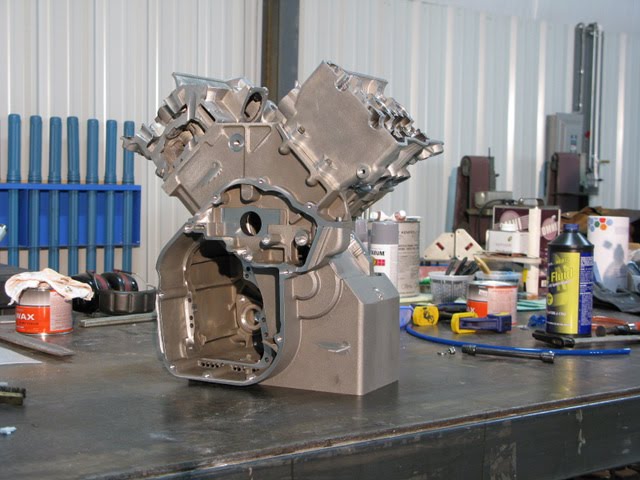
Now that we have a girdle, top, and a couple of heads the time is ripe for some assembly shots. I'll let the images speak for themselves...


Short Block:


Long block:


The overall engine assembly is very short front to rear to enable a long swingarm in a short wheelbase. The resultant slight additional height compared to a normal I4 is easily accommodated by the unique chassis needed for the Hossack-style front suspension.

Tuesday, September 7, 2010

Finishing the Girdle Machining

This blog post is dedicated to Chris Hodgson from San Jose BMW. I saw Chris and his crew at the BUB Bonneville motorcycle speed trial event last week while helping wrench for Scott Kolb on his 125cc partial streamliner. Scott set a new 2 way record of 146.7mph on the last day of the event after lots of tweaking. There's an article over at Hell For Leather on the effort. The trip was lots of fun, especially when a record is set. Every speed lover needs to go to Bonneville. It's only 2 hrs outside of Salt Lake City and besides having no speed limit also presents an awesome vista in any direction.


Back to the topic at hand, I had the short block with me for display purposes and Chris Hodgson was like 'when did you do that machining, the blog is not up to date, what are you waiting for!!!!!' Being chastised by an internet follower compelled me to get my ass back in gear. That fact that it was a person who is a world renowned BMW tuner made it go into high gear! Chris and crew also took a record with their BMW HP2 so it was a happy pit area all around.

Chris, this update is for you and hopefully I will be able to work on the project and update the blog regularly.

Now on to our regular programming...........

After the last post, which was machining the girdle split surface, we are up to the balance of machining on the girdle part. We were up to this point on the part:

Oil gasket and split surface machined:


The next step is to machine the girdle subplate then complete the part machining. The subplate screws to the oil pan surface and is accurately aligned to the trunnion table with dowel pins.


The first set of features to be machined is the crankshaft main bearing split surface:

Facing:


Drilling/tapping.......


Then the 4th axis is indexed 90 degrees and the clutch side is machined. there is a bunch of profiling for the cassette transmission side plate, trans and oil shaft bearing bores, gear clearance, and misc threaded holes.

Cassette mounting flange:

Gear clearance:


Roughing the bearing bores:


Once these deep bores and pockets are done the 4th gets rotated -180 degrees to machine the output sprocket side. The features on this side are the generator cover surface, oil filter mount, oil pump drive and pressure chambers, and starter bore. Yes, a starter motor! No rollers, no bumping, just press the magic button.


Facing gasket surfaces:

Some operations are pushing the limit of tool stability, like this 1" dia x 8" long insert end mill:


Starter motor mounting hole:

Gerotor porting:

The oil pump is a gerotor supplied by Melling, a high quality OEM/aftermarket automotive parts manufacturer. This style pump is highly efficient and compact when properly packaged. A lot of design assistance for the entire oil pump circuit was provided by Marc Goulet of Melling. Marc is also a motorcyclist and was kind enough to donate his time and put up with my unending questions on the subtle details of high performance oil system design. Marc has been involved in the design of some top level F1 engine oiling systems so he is definitely the person to ask in this field.

Inner and outer oil pump gerotor:


These parts fit into dual eccentric pockets that have CNC porting designed to allow high flow with minimal power losses.

Those 3 machining positions contain all of the high tolerance operations. Now on to some less critical ones:

Oil drain hole:


The position of the subplate is then indexed 90 degrees on the trunnion table and we machine the:

Upper engine mount:


Lower engine mount:


Starter mount:


That covers the majority of the machining on the girdle. Bearing bores will be finish machined as part of a complete crankcase assembly.

It ends up being one sweet looking part:


Stay tuned for more soon!

Friday, July 2, 2010

Machining the Gasket Split Surface


Now that we've gotten accurate mounting features and a matching fixture plate we can start machining the rest of the part.


These operations are relatively simple, some facing, drilling and a bit of spot-facing. I'll be machining the following features:
  • face the main gasket surface

  • drill/main bearing stud holes

  • drill/tap crankcase attachment bolt holes
  • drill cylinder head oil drain holes
  • spotface/drill oil passage in filter area

That's all I have for now. I hope everybody has a fun 4th of July holiday. Until next time.


Chris

Machining the Girdle

Now that the girdle has been scanned and determined to be accurate, I can reference known location features to accurately position and clamp the part to the mill bed.


Once rigidly clamped onto the bed, chips will start to fly.

Literally.


  • machine fixture plate and mount part


Now we're ready to machine the rest of the features using the 4th axis setup. Unfortunately, it's time to shift to some customer work for a few days.

Monday, June 21, 2010

QC on the Crankcase Girdle


The sample casting for the crankcase lower section just came in. This part contains the crankshaft lower bearing caps, oil pump/filter and drive system, and the transmission and clutch. Although it looks visually more complicated than the crankcase top, it is a simpler piece to cast in that there is only one internal passages requiring a buried core, namely for the oil pump pressure area.

The placement of this core is less critical than those for the cylinder bores because of the lower pressure and thermal stresses this area experiences. This core forms the pump inlet and outlet ports, high pressure chamber, pressure relief valve port, and oil filter mounting boss details all in one piece. One of the benefits of the casting process is that part complexity is not penalized as it is with billet parts.


The QC process used on this part will be the same as for the crankcase top:

  • scan


  • overlay to CAD to verify fidelity to the CAD model.


This sample part was dimensionally excellent. There are a couple of areas I may modify after going through the part's CNC programming process. I'll know more as the part moves through the various machining stages.

That's all for now.

Chris

Monday, June 14, 2010

Part 2-Machining the Crankcase Top

Now that the crankshaft split surface and related features are machined the rest of the machining process for the part is easier. If all of the previous scanning, QC and OP1 processes went correctly then this stage should be a breeze. Hopefully I don't regret that statement!

We are starting here, a part located on the fixture plate with the majority of machine work yet to be done.

The next machining steps are as follows:
  • machine the generator side features: gasket surface, mounting holes, and main galley oil passages, and logo cleanup


  • machine clutch side features: gasket surface, mounting holes

The logo on this side was left as-cast to see which looks better. I prefer the milled one.


The part then gets rotated 90 degrees for the following operations:

Bank1:
  • Face deck surface with 6" face mill. The 6" diameter tool machines the deck surface with one sweep, crating a very flat and consistent surface.

  • Rough mill cylinder bores. I use a long 3/4" diameter 6" long 3 flute carbide end mill held in a milling chuck, both from Mari Tool, for maximum rigidity. The cut was deep but clean with no chatter. It was a good enough finish to send directly to the platers but I wanted the extremely straight bore that a finish pass with a boring head would provide.

  • Cleanup coolant port passages. This was step one in showing how well the internal coolant ports were aligned to t he core and cope of the mold. One bank had excellent alignment, one bank needed a bit of tweaking, but this is the area where we expected a large tolerance stackup. Harmony will likely revise the gauges used to place the cores to all

  • drill and tap cylinder head bolts and dowel holes


  • Finish cylinder bore to .008" oversize in preparation for nickel silicon carbide plating by Millennium Technologies. This was done using one of the single point boring bars from Microbore with a TCGT ground and polished carbide insert.


Then repeat the same operations for Bank 2.


Valley:
  • coolant ports gasket surface milling
  • coolant port mounting holes drill and tap
  • oil pressure sensor drill and tap


So far so good. No crashes, although I did nearly break a couple of tools from unforeseen interference between the trunnion tailstock and the long tools installed in the toolchange umbrella.

In general the entire machining process was fault-free. The stiffness of the trunnion from Martin Mfg. was excellent. The large tools cut as if the part was clamped directly to the machine table, no ringing, chatter, or other abnormal tool behavior. The bore finish from the Microbore boring bars is better than expected.

Once the casting patterns have some slight revisions done they'll run 5 more parts that will then get machined.

I am very satisfied with the results so far. The sample casting for the girdle part just arrived, so now I can start directly on that and hopefully have just as good a time.

That's all for now.

Chris