As with hibernating bears, hibernating motorcyclists eagerly await the first glimmers of spring to start the trek to Daytona, the first major race event of the year. This year I am lucky enough to get some free time and head down there with Scott Kolb and his Bonneville LSR team. In addition to spending some time relaxing in warm weather we will be hanging around the Celtic Race Team's garage to lend a hand if needed. Barry scored a big win this year in partnering with Fast by Ferracci to run Ducati's 848EVO in the Daytona Sportbike series. This bike is a sweet track tool and Barry's rider, PJ Jacobsen, showed just how much the competition should be worrying by topping the timesheets at the Daytona tire test.
In the interest of making this a more interesting trip I spent some time getting the engine assembled into a convincing looking long block while Scott whipped up a sweet wheeled engine stand. We'll be hanging out in the paddock with the engine trying to get some exposure in the AMA scene. If we're lucky we'll get some time in the Celtic pits with Eraldo Ferracci and see if he has any words of wisdom on our project. If you see a coupe of guys wheeling around an engine with no bike attached, stop by and say hello.
Sorry about the crappy cell phone picture but I was rushing to get the engine assembled in time to put it into Scotts' trailer for the trip down to Florida. I don't think we would be able to bring it on the place as carry-on luggage!
Friday, March 4, 2011
Machining the Oil Pump Cover
This installment covers the machining of the oil pump drive housing but first a little background on the oil pump/system design.
There are three main types of oil pumps to choose from: plunger style, spur gear style, and gerotor style. Plunger style pumps have been made obsolete by the improved gear and gerotor style pumps so will immediately be discarded. A couple of images showing the gear and gerotor style pumps can be found at this link. Since I've never designed an engine oiling system before I tried to find an expert to assist me. A few phone calls to some noted engine tuners all pointed to the same source: Marc Goulet. Marc, formerly of Nichols Portland and now at Melling Engine Parts, Inc., has extensive experience in designing performance engine oiling systems. He has done systems for various F1 cars and several MotoGP bikes, including the Ducati Desmosedici. Needless to say, this is the person I was looking for. Marc was extremely helpful, first educating me on some of the details of oiling system design, then critiquing my designs until we came up with a system he was happy with. His first recommendation was to go with the gerotor pump style. Less oil abuse and higher efficiency were all it took to convince me. There are a lot of details to be considered, some of which cannot be ignored under pain of complete oiling system failure, some of which when ignored result only in a slightly less efficient system. I wanted to cover all the bases: have a reliable and efficient oiling system that provides just enough cool, clean oil to all of the appropriate components while using a minimum of power. A design guide from Nichols Portland was a big help in getting the design in the ballpark. The guide is available online here if you fill out your personal information.
The first step was choosing an appropriately sized gerotor pair that had existing tooling. We were able to use one of Melling's stock products as shown in the following photo:
After several revisions we had a system Marc was happy with: generously sized inlet porting to minimize filling resistance on the inlet side of the pump, appropriate porting and venting to prevent unbalanced operation, and a large and strategically located bypass valve to reduce unnecessary pumping losses. Now that I had a good design, it needed to be fabricated.
Half of the pump housing and port geometry was located in the girdle casting as shown in the following picture:
The gerotor outer rotor sits in the main pocket and the inner rotor is eccentrically mounted and driven by a gear reduced shaft from the primary drive gear. The machining of this has already been reviewed so we will move on to the cover plate machining. The cover plate serves several functions: it has half of the inlet porting, outlet shadow porting, outboard drive shaft bearing support, and appropriate venting to prevent undesirable pumping losses. It also seals the jackshaft bearing and gerotor pocket from leaks.
The machining process is a repeat of the technique used so far: machine the functional side of the part from an appropriately sized billet, trim the excess off with the bandsaw, then machine soft jaws, flip the part and machine the external surfaces.
Here's the billet being held in the vice prior to machining:
Here's the part after the first machining operation:
The large boss/pocket on the left side of the part matches up with the porting in the girdle casting to provide a leak-proof path through the gerotor.
From here I machined soft vice jaws to hold the part from the 2 circular bosses then faced and pocketed the external surfaces as needed.
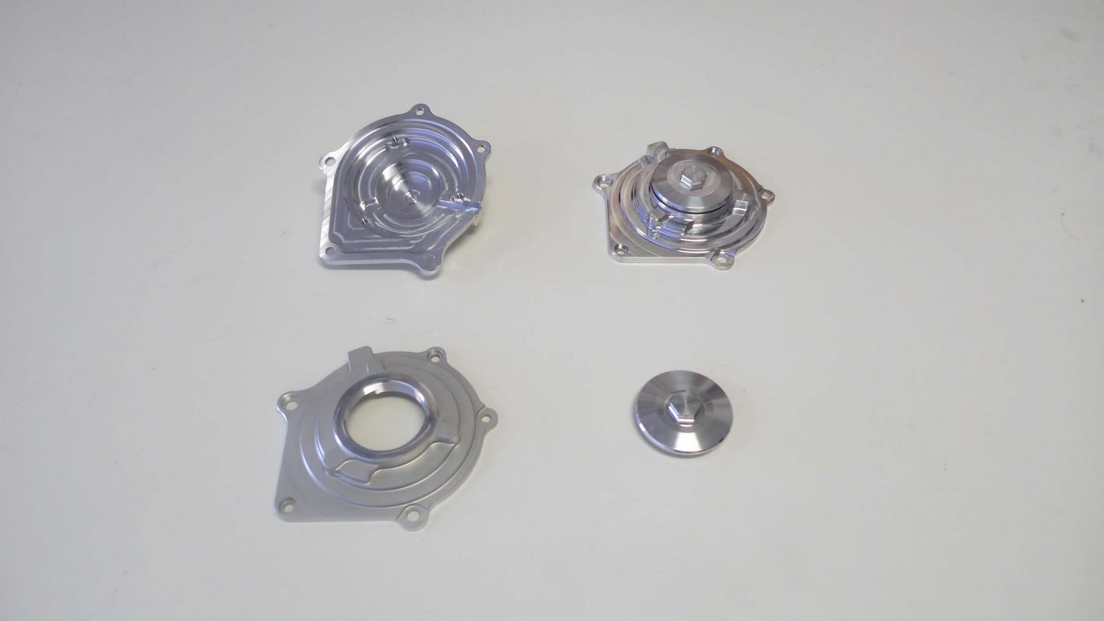
Repeat as needed and I ended up with 3 finished parts that look great and are all well within tolerance:
That's all for now. The next installments will be on machining the crankshaft cam drive sprocket teeth and some more of the engine side covers.
Until next time......
There are three main types of oil pumps to choose from: plunger style, spur gear style, and gerotor style. Plunger style pumps have been made obsolete by the improved gear and gerotor style pumps so will immediately be discarded. A couple of images showing the gear and gerotor style pumps can be found at this link. Since I've never designed an engine oiling system before I tried to find an expert to assist me. A few phone calls to some noted engine tuners all pointed to the same source: Marc Goulet. Marc, formerly of Nichols Portland and now at Melling Engine Parts, Inc., has extensive experience in designing performance engine oiling systems. He has done systems for various F1 cars and several MotoGP bikes, including the Ducati Desmosedici. Needless to say, this is the person I was looking for. Marc was extremely helpful, first educating me on some of the details of oiling system design, then critiquing my designs until we came up with a system he was happy with. His first recommendation was to go with the gerotor pump style. Less oil abuse and higher efficiency were all it took to convince me. There are a lot of details to be considered, some of which cannot be ignored under pain of complete oiling system failure, some of which when ignored result only in a slightly less efficient system. I wanted to cover all the bases: have a reliable and efficient oiling system that provides just enough cool, clean oil to all of the appropriate components while using a minimum of power. A design guide from Nichols Portland was a big help in getting the design in the ballpark. The guide is available online here if you fill out your personal information.
The first step was choosing an appropriately sized gerotor pair that had existing tooling. We were able to use one of Melling's stock products as shown in the following photo:
After several revisions we had a system Marc was happy with: generously sized inlet porting to minimize filling resistance on the inlet side of the pump, appropriate porting and venting to prevent unbalanced operation, and a large and strategically located bypass valve to reduce unnecessary pumping losses. Now that I had a good design, it needed to be fabricated.
Half of the pump housing and port geometry was located in the girdle casting as shown in the following picture:
The gerotor outer rotor sits in the main pocket and the inner rotor is eccentrically mounted and driven by a gear reduced shaft from the primary drive gear. The machining of this has already been reviewed so we will move on to the cover plate machining. The cover plate serves several functions: it has half of the inlet porting, outlet shadow porting, outboard drive shaft bearing support, and appropriate venting to prevent undesirable pumping losses. It also seals the jackshaft bearing and gerotor pocket from leaks.
The machining process is a repeat of the technique used so far: machine the functional side of the part from an appropriately sized billet, trim the excess off with the bandsaw, then machine soft jaws, flip the part and machine the external surfaces.
Here's the billet being held in the vice prior to machining:
Here's the part after the first machining operation:
The large boss/pocket on the left side of the part matches up with the porting in the girdle casting to provide a leak-proof path through the gerotor.
From here I machined soft vice jaws to hold the part from the 2 circular bosses then faced and pocketed the external surfaces as needed.
Repeat as needed and I ended up with 3 finished parts that look great and are all well within tolerance:
That's all for now. The next installments will be on machining the crankshaft cam drive sprocket teeth and some more of the engine side covers.
Until next time......
Friday, February 18, 2011
Finishing the Generator Cover
I managed to stay late and squeeze in some more machining to finish up the generator cover. After ending the last post with the first setup finished I then machined a simple fixture plate to locate on the interior features of the part. it used the stator mounting bolts and a couple of mounting holes with dowel pins to keep the part accurately aligned with the previous operation.
Second operation fixture plate:
Loaded in the mill with a part installed:
After rough machining:
With it's brothers:
I gave one a light glass bead blasting to reduce the reflectivity of all the shiny machined surfaces. The result looked great:
The round cap part has M50x1.25 metric threads that were made on a lathe with a normal threading cycle, like most externally threaded parts. The cover part then needed an internal M50x1.25 thread which would need a special M50x1.25 tap, which would be very expensive, or I could make the thread using a thread mill, which is the option we used. Thread milling uses a 60 degree V-shaped cutter that is moved in a helical path that corresponds to the thread profile. If everything is done properly you end up with a very clean and accurate thread without the need for a tap.
Here's a video of the thread milling operation. It is done 3-4 times with an incrementing depth of cut and a small finish path.
These parts are now finished and the next step is to make the gerotor pump and bearing shaft cover. Look for a post sometime next week for more.
Until next time.
Second operation fixture plate:
Loaded in the mill with a part installed:
After rough machining:
With it's brothers:
I gave one a light glass bead blasting to reduce the reflectivity of all the shiny machined surfaces. The result looked great:
The round cap part has M50x1.25 metric threads that were made on a lathe with a normal threading cycle, like most externally threaded parts. The cover part then needed an internal M50x1.25 thread which would need a special M50x1.25 tap, which would be very expensive, or I could make the thread using a thread mill, which is the option we used. Thread milling uses a 60 degree V-shaped cutter that is moved in a helical path that corresponds to the thread profile. If everything is done properly you end up with a very clean and accurate thread without the need for a tap.
Here's a video of the thread milling operation. It is done 3-4 times with an incrementing depth of cut and a small finish path.
These parts are now finished and the next step is to make the gerotor pump and bearing shaft cover. Look for a post sometime next week for more.
Until next time.
Thursday, February 17, 2011
Starting on the Generator Cover
Back to making chips! This post is the first part of fabricating the generator side engine cover. this is a 2 piece cover with a threaded inspection port to give access to the end of the crankshaft.
I'm doing the same process as used with many other parts: first machine the inside surfaces from a billet of aluminum, then in a following post I'll machine a fixture plate that locates to these features and then machine the external surfaces of the part.
The internal features and mounting holes are critical to the correct placement of the stationary stator with respect to the crankshaft mounted rotor. By machining these in one setup I am assuring high accuracy between these features.
Skipping directly to the chase (I forgot to photo intermediate machining steps!) Here's 3 sets of parts: 3 completed access ports and 3 1/2 machined side covers.
Threaded inspection port:
This was a 3 operation part: first turn the thread, counterbore and o-ring sealing groove, then turn around and turn the outer profile, then switch to the mill to make the 17mm hex for wrenching.
Generator side cover at the halfway mark:
This operation created the outer profile, mounting and locating holes, and mounting holes for the Electrx race stator. This product from Electrex is a low profile race generator kit meant to replace the larger systems found on production Japanese motorcycles at about 1/5 the cost of a similar race kit item from any of the manufacturers. Build quality was excellent and they are great source for low volume OEM sourcing of generator components.
Here's the stator bolted in place with the 3 phase wiring exiting though a slot in the gasket surface:
Next up is capping the ends of the valve covers and then final machining of the welded cylinder heads and valve covers.
Until next time.
I'm doing the same process as used with many other parts: first machine the inside surfaces from a billet of aluminum, then in a following post I'll machine a fixture plate that locates to these features and then machine the external surfaces of the part.
The internal features and mounting holes are critical to the correct placement of the stationary stator with respect to the crankshaft mounted rotor. By machining these in one setup I am assuring high accuracy between these features.
Skipping directly to the chase (I forgot to photo intermediate machining steps!) Here's 3 sets of parts: 3 completed access ports and 3 1/2 machined side covers.
Threaded inspection port:
This was a 3 operation part: first turn the thread, counterbore and o-ring sealing groove, then turn around and turn the outer profile, then switch to the mill to make the 17mm hex for wrenching.
Generator side cover at the halfway mark:
This operation created the outer profile, mounting and locating holes, and mounting holes for the Electrx race stator. This product from Electrex is a low profile race generator kit meant to replace the larger systems found on production Japanese motorcycles at about 1/5 the cost of a similar race kit item from any of the manufacturers. Build quality was excellent and they are great source for low volume OEM sourcing of generator components.
Here's the stator bolted in place with the 3 phase wiring exiting though a slot in the gasket surface:
Next up is capping the ends of the valve covers and then final machining of the welded cylinder heads and valve covers.
Until next time.
Saturday, February 12, 2011
Kolb Comes Through
Many thanks to Scott Kolb of Kolb Machine for delivering 2 perfectly capped and smoothed cylinder heads. Scott is a fabrication ace and it is him who I turn to when my ham-fisted hand work simply will not be up to snuff. He is also an accomplished builder in his own right, having several land speed records under his belt and several more in his sights. His blog site shows a lot of cool stuff on his LSR project. There is also some great footage from his visit to the A2 wind tunnel in North Carolina, the heart of NASCAR territory. The visit was very productive and informative for both learning about his existing partial streamliner and doing tests on shapes for his future 200+mph 125cc full streamliner. It was my first wind tunnel test and hopefully not my last.
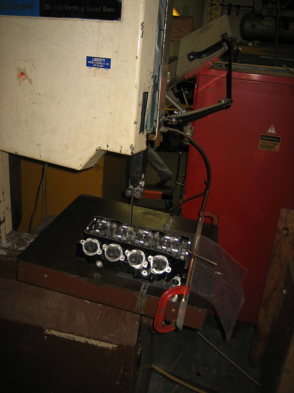
I had 2 sets of ported heads and kit cams purchased from Attack Kawasaki from one of their last Formula Xtreme bikes when that series still allowed significant engine modifications. These heads were sectioned on a bandsaw and cleaned up on the mill to leave the camchain tunnel and adjacent 2 cylinders.
Bandsaw cutting:
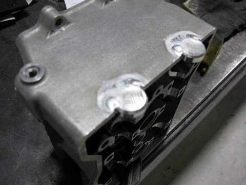
Fully welded:
I had 2 sets of ported heads and kit cams purchased from Attack Kawasaki from one of their last Formula Xtreme bikes when that series still allowed significant engine modifications. These heads were sectioned on a bandsaw and cleaned up on the mill to leave the camchain tunnel and adjacent 2 cylinders.
Bandsaw cutting:
Cleaning up surface on mill with face mill:
I then stripped the paint off the parts and shipped them up to Scott. He proceeded on the 2 step process first documented in an earlier post, Head Weld Test. The 2 piece cap is to insure the internal separation from the oil and cooling passages remains separated.
Cutting out the cap plates:
Top cap plate unwelded/welded:
We installed extra valves and springs during the process to ensure the valve seats did not slide out of position due to the high heat input during TIG welding.
Fully welded part:
We decided to also fill in the cam bore 1/2 circular cutouts to make the gasket surface a single plane to allow using a waterjet cut Cometic gasket
Filling in cam journal external bosses:
Fully welded:
Trimmed:
Scott then ground out all the welds giving the part a very clean and manufactured look.
From here I will remove the valves/springs and mount the head on our trunnion fixture to clean up the gasket mounting surface. Some custom gaskets are on the way from Cometic to keep all the oil inside and we're a few steps closer to having a complete engine.
Until next time...
Thursday, February 10, 2011
Machining the Crankshaft Connecting Rod Journals
I was able to get some more time in on Peter's mill and got the journal machining done on all 3 crankshafts. After the last step the cranks were turned but did not have the offset journals machined, as shown in the following picture:
This step moved the parts from the lathe to the mill. I hold the right side of the crank in a 3J collet and supported the outboard side with a tailstock with a dead center. The setup is shown in the following picture:
The process is the same as the aluminum test part, except the spindle speed and feeds were much slower, the depth of cut was less, and I used a roughing and finishing end mill. The finishing end mill was custom ground to have a flat end which minimized the uneven surface that the test part ended up with.
The roughing end mill has a serrated cutting surface and provides an aggressive edge to remove large amounts of material, allowing the finish end mill to only remove the last .02", last longer, and hold tighter tolerances. The end mills were purchased from Mari Tool and held in a 3/4 milling chuck for maximum rigidity.
Now on to some cutting shots. First roughing in a step pattern produces a square journal:
Once both journals are roughed out leaving a square the next operation employs a 4th axis move to create the rounded thrust and journal surfaces:
Here's a couple of videos showing the finishing passes for both the thrust and journal surfaces:
and
The resulting surface finish and accuracy were excellent. Here's a quick spin of the final part.
The great part about CNC is now I ran the same program 2 more times and ended up with 3 great parts.
Next steps for the crankshaft are to machine the camchain sprocket teeth and drill the oil holes. Hopefully i'l get to those operations next week and be ready to ship them out for gear hobbing and plasma nitriding shortly after.
That's all for now.
This step moved the parts from the lathe to the mill. I hold the right side of the crank in a 3J collet and supported the outboard side with a tailstock with a dead center. The setup is shown in the following picture:
The process is the same as the aluminum test part, except the spindle speed and feeds were much slower, the depth of cut was less, and I used a roughing and finishing end mill. The finishing end mill was custom ground to have a flat end which minimized the uneven surface that the test part ended up with.
The roughing end mill has a serrated cutting surface and provides an aggressive edge to remove large amounts of material, allowing the finish end mill to only remove the last .02", last longer, and hold tighter tolerances. The end mills were purchased from Mari Tool and held in a 3/4 milling chuck for maximum rigidity.
Now on to some cutting shots. First roughing in a step pattern produces a square journal:
Once both journals are roughed out leaving a square the next operation employs a 4th axis move to create the rounded thrust and journal surfaces:
Here's a couple of videos showing the finishing passes for both the thrust and journal surfaces:
and
The resulting surface finish and accuracy were excellent. Here's a quick spin of the final part.
The great part about CNC is now I ran the same program 2 more times and ended up with 3 great parts.
Next steps for the crankshaft are to machine the camchain sprocket teeth and drill the oil holes. Hopefully i'l get to those operations next week and be ready to ship them out for gear hobbing and plasma nitriding shortly after.
That's all for now.
Monday, February 7, 2011
And now for something completely different
After working on all these engine parts I got a bug to shift focus and to make some inroads on the pile of chassis parts that need to be made. My first choice was to make the upright legs for the front suspension. These legs are central to the variable flex idea that is incorporated in the front suspension. Instead of following the current ideas on overall bike flexibility which uses stiff telescopic forks and a slightly flexible chassis, I prefer to have the flex where it is needed-at the wheel. Telescopic fork equipped bikes don't have much of an option here- the forks needs to be relatively rigid, otherwise they would bind up when flexing under braking load, preventing smooth suspension movement. With the linkage suspension I am using it is possible to have a very stiff chassis and a-arm structure to allow smooth suspension action and accurate wheel location yet have flex built into the upright legs to accommodate small bumps and irregularities in the surface when leaned far over.
From the years spent campaigning my single cylinder racer I have a good idea of the directional stiffness that will produce good results. No, I won't go into specifics here on what the stiffness ratios are. As expected, maximum stiffness is needed in the braking direction and much less needed in the transverse direction. The initial uprights I designed worked well, but was a bit complex to make quick copies of. I then moved on to a much simpler design using rectangular steel, some with welded on stiffening plates to tweak the stiffness as testing dictated. The latest version of the front suspension uses some old and some new to result in a low friction assembly with easily characterized controlled flex characteristics.
First upright design using suspended headstock design:
This design worked very nicely but was a bit complex to make variations on. The suspended headstock and all ball bearing upright mounts provided smooth action and good feel but at a weight penalty to later, simpler designs.
Second design style using spherical bearings (bearings not shown):
This design had the benefit of being easy to replicate with subtle stiffness variations but I found the spherical rod end bearings reduced feel and required frequent replacement in order to maintain optimum performance.
Final version for the V4 project bike:
This version separates the parts into a bearing carrier and legs that bolt on. It enables easy modifications to the stiffness by making new leg parts with varying dimensions yet keeps the bearing mount arrangement stiff. The weight is in between the first two designs, a good overall compromise in my opinion. The upright legs will be machined today.
As with most billet parts I started with a large plate that both parts could fit in. I bolted this directly to the CNC table and machined the mounting pads and axle holes as shown in the following image:
I then machined a fixture baseplate that would locate on these premachined features and allow me to complete the part:
The fixture locates on the machine table with dowel pins allowing easy and accurate setup for making more parts.
I then cut out the individual parts leaving extra stock around the perimeter and bolted them to the fixture plate as shown:
Next came the pocketing and chamfer operations:
Resulting in a sweet looking part:
Mirroring the toolpaths allowed me to create the 2nd part with a minimum of hassle resulting in a very stiff looking assembly: This design also makes use of the latest radial mount Brembo billet calipers for the ultimate in progressive braking feel.
I don't mention it often enough so a big thank you goes out my shopmate to Peter H. for allowing me essentially unlimited use of his 4 axis CNC mill. Without access to his machine I'd be making much lower quality parts on my old BP 3 axis relic. And I'd still be figuring out how to fit the engine castings on it!
In the next few days I hope to move on to the upright bearing housing and handlebar mount, both of which need the 4th axis and trunnion table.
Until then.....
From the years spent campaigning my single cylinder racer I have a good idea of the directional stiffness that will produce good results. No, I won't go into specifics here on what the stiffness ratios are. As expected, maximum stiffness is needed in the braking direction and much less needed in the transverse direction. The initial uprights I designed worked well, but was a bit complex to make quick copies of. I then moved on to a much simpler design using rectangular steel, some with welded on stiffening plates to tweak the stiffness as testing dictated. The latest version of the front suspension uses some old and some new to result in a low friction assembly with easily characterized controlled flex characteristics.
First upright design using suspended headstock design:
This design worked very nicely but was a bit complex to make variations on. The suspended headstock and all ball bearing upright mounts provided smooth action and good feel but at a weight penalty to later, simpler designs.
Second design style using spherical bearings (bearings not shown):
This design had the benefit of being easy to replicate with subtle stiffness variations but I found the spherical rod end bearings reduced feel and required frequent replacement in order to maintain optimum performance.
Final version for the V4 project bike:
This version separates the parts into a bearing carrier and legs that bolt on. It enables easy modifications to the stiffness by making new leg parts with varying dimensions yet keeps the bearing mount arrangement stiff. The weight is in between the first two designs, a good overall compromise in my opinion. The upright legs will be machined today.
As with most billet parts I started with a large plate that both parts could fit in. I bolted this directly to the CNC table and machined the mounting pads and axle holes as shown in the following image:
I then machined a fixture baseplate that would locate on these premachined features and allow me to complete the part:
The fixture locates on the machine table with dowel pins allowing easy and accurate setup for making more parts.
I then cut out the individual parts leaving extra stock around the perimeter and bolted them to the fixture plate as shown:
Next came the pocketing and chamfer operations:
Resulting in a sweet looking part:
Mirroring the toolpaths allowed me to create the 2nd part with a minimum of hassle resulting in a very stiff looking assembly: This design also makes use of the latest radial mount Brembo billet calipers for the ultimate in progressive braking feel.
I don't mention it often enough so a big thank you goes out my shopmate to Peter H. for allowing me essentially unlimited use of his 4 axis CNC mill. Without access to his machine I'd be making much lower quality parts on my old BP 3 axis relic. And I'd still be figuring out how to fit the engine castings on it!
In the next few days I hope to move on to the upright bearing housing and handlebar mount, both of which need the 4th axis and trunnion table.
Until then.....
Subscribe to:
Posts (Atom)