Friday, June 17, 2011

When the mill is busy....

Switch to the lathe.  Got a bit of time in to make some parts for the front end, specifically the steering stem.  Although my bike does not have forks, it does have a steering stem, one that moves with suspension travel but does not pivot with steering.  The design is a throwback to my original Mk1 chassis that used a combination of tapered roller and deep groove ball bearings instead of spherical rod ends at the upright pivot.  Sorry for the vintage shot but those were the early days of digital.....


Those were the early days (2001) of nearly zero rake and an air cooled Rotax single.  In case anyone was wondering, do not use Daytona as a maiden voyage for a race bike, frame still warm from welding.  We both survived but it was a lesson learned!

I've almost come full circle, having experimented with various bearing configurations in the quest to maximize feel and minimize friction and hysteresis in a compact package. This is an area in front end design where just equaling the feel and feedback quality of telescopic forks will be a very good result.  With a linkage and multiple pivots there are many more areas where the vibrational energy that is feedback can be lost.  Careful detail design can minimize this loss and is a necessity for high performance race applications but the solutions are not always obvious.  For a while I was using high quality Aurora spherical rod ends that gave me easy adjustability but lacked in extended lifespan and were relatively expensive.  The bearings in the current version are different styles from what was originally used and should be an improvement in feel and packaging.

Back to today's part, the steering stem.  It serves to connect both suspension a-arms and provides a pivot axis for the wheel/legs/upright assembly.  It has 2 bearing journals that define the steering axis, a jam nut thread, and 2 cross holes once for each a-arm.

Herre's the bare part:


The first step is to turn the main part geometry from bar stock on the CNC lathe.


Close the door, press the button and...

Open the door and presto, a part:

To assist in getting the bike dialed in I had to make several different versions of the stem.  Think of them as different triple clamps and you won't be far off.  In combination with other interchangeable parts they allow near independent adjustment of several important chassis parameters.

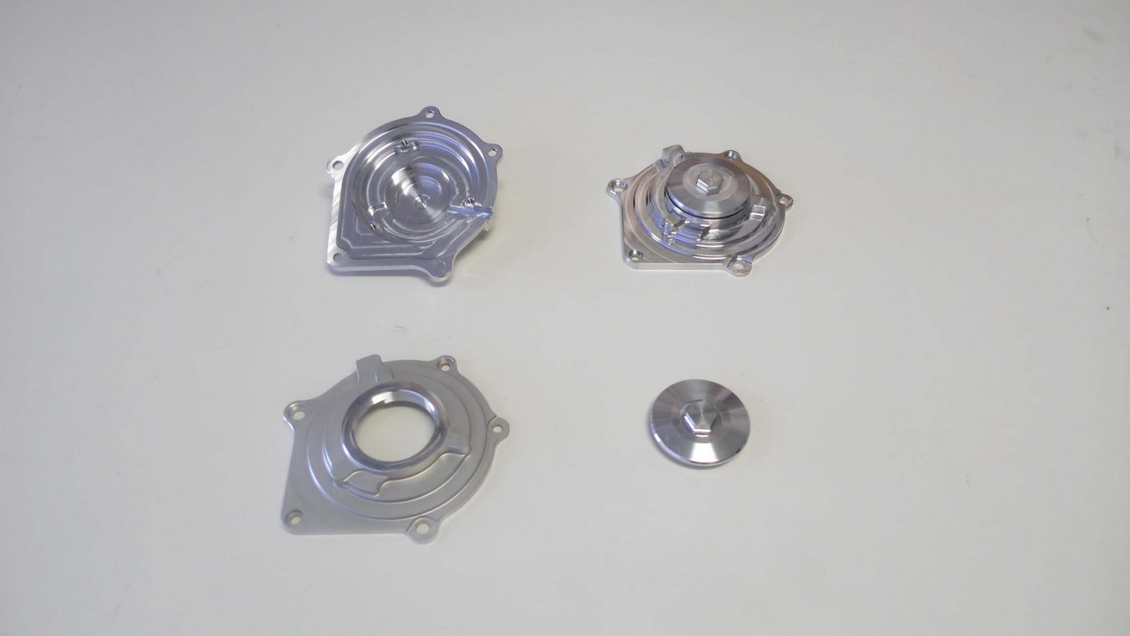
 Here's the 3 different part geometries with the steering bearings that will be used.


These parts will now need to go into a 4th axis mill setup where I will add the flats and cross holes, finishing them.

That's all for now.

Saturday, May 21, 2011

Finally another update

Sorry for the extended interval since the last update.  I've been trying to get as much paid work as possible while it is available, the life of an independent is feast or famine, and there hasn't been much feasting lately!

Anyway I was able to get some extra time and sanity and made some progress on the transmission cassette cover.  These parts are made from a billet of 7075-T651 aluminum.  They hold the two transmission shafts, the shifter drum, 2 shift forks and shafts, and the selector mechanism.  The transmission design allows the entire assembly to be pulled from the clutch side of the engine without having to do any other engine disassembly, making for easy ratio changes.  As we are using Kawasaki transmission parts there are several available ratios from the race kit.

Here's the 2 blocks of 7075 waiting for machining:


No fixture needed for this first operation, just a wide open vice:

This side of the part was pretty straightforward, no special machining operations needed.  The next side will bore the bearing pockets using some of the custom boring heads I had made.  After about 15min of machining you end up with 1/2 a part and a lot of chips:


Now insert the 2nd billet and repeat:
I'll be machining the other side sometime in the next few days so an update should not be an extended wait.  I hope to be able to put a big push in the coming month and get this baby running ASAP.


That's all for now.


Chris

Monday, March 14, 2011

Back from Daytona

Just got back from Daytona and had a great time enjoying some nice weather and motorcycle racing.  What more can one ask for?  Well, we can ask for the AMA to properly run an uninterrupted 200 mile race like they used to be able to do.  This makes it 3 years in a row with screw-ups. Mandatory front tire change?  That's a big ball to be dropped by Dunlop.  When a company signs up to provide equipment for a spec series that equipment should not fail, potentially putting riders at risk of injury.  I saw PJ Jacobson's tire after his crash and wondered how squirrely the bike must have felt on the banking with missing chunks of rubber.  Not confidence inspiring to say the least.

Back to fun topics.  While we were there I toted the engine around the paddock and showed it to several people and got some interesting feedback.  The sweet engine stand was whipped up by Scott Kolb, as usual filling in the aesthetic gaps I leave.


We met with Barry Gilsenan and Eraldo Ferracci, both of who were impressed with the progress so far and excited to get to a stage where they can actively help the project move forward.


We also met with Skip Dowling, president of Orient Express, to thank him for the sponsorship on engine parts, both OEM Kawasaki and aftermarket, that he is providing.  All in all it was a productive trip and now I'm inspired to get this motor running ASAP.

That's all for now.

Friday, March 4, 2011

Trip to Daytona

As with hibernating bears, hibernating motorcyclists eagerly await the first glimmers of spring to start the trek to Daytona, the first major race event of the year.  This year I am lucky enough to get some free time and head down there with Scott Kolb and his Bonneville LSR team.  In addition to spending some time relaxing in warm weather we will be hanging around the Celtic Race Team's garage to lend a hand if needed.  Barry scored a big win this year in partnering with Fast by Ferracci to run Ducati's 848EVO in the Daytona Sportbike series.  This bike is a sweet track tool and Barry's rider,  PJ Jacobsen, showed just how much the competition should be worrying by topping the timesheets at the Daytona tire test.

In the interest of making this a more interesting trip I spent some time getting the engine assembled into a convincing looking long block while Scott whipped up a sweet wheeled engine stand.  We'll be hanging out in the paddock with the engine trying to get some exposure in the AMA scene.  If we're lucky we'll get some time in the Celtic pits with Eraldo Ferracci and see if he has any words of wisdom on our project.  If you see a coupe of guys wheeling around an engine with no bike attached, stop by and say hello.


Sorry about the crappy cell phone picture but I was rushing to get the engine assembled in time to put it into Scotts' trailer for the trip down to Florida.  I don't think we would be able to bring it on the place as carry-on luggage!

Machining the Oil Pump Cover

This installment covers the machining of the oil pump drive housing but first a little background on the oil pump/system design.

There are three main types of oil pumps to choose from: plunger style, spur gear style,  and gerotor style.  Plunger style pumps have been made obsolete by the improved gear and gerotor style pumps so will immediately be discarded.  A couple of images showing the gear and gerotor style pumps can be found at this link.  Since I've never designed an engine oiling system before I tried to find an expert to assist me.  A few phone calls to some noted engine tuners all pointed to the same source:  Marc Goulet.  Marc, formerly of Nichols Portland and now at Melling Engine Parts, Inc., has extensive experience in designing performance engine oiling systems.  He has done systems for various F1 cars and several MotoGP bikes, including the Ducati Desmosedici.  Needless to say, this is the person I was looking for.  Marc was extremely helpful, first educating me on some of the details of oiling system design, then critiquing my designs until we came up with a system he was happy with.  His first recommendation was to go with the gerotor pump style.  Less oil abuse and higher efficiency were all it took to convince me.  There are a lot of details to be considered, some of which cannot be ignored under pain of complete oiling system failure, some of which when ignored result only in a slightly less efficient system.  I wanted to cover all the bases: have a reliable and efficient oiling system that provides just enough cool, clean oil to all of the appropriate components while using a minimum of power.  A design guide from Nichols Portland was a big help in getting the design in the ballpark.  The guide is available online here if you fill out your personal information.

The first step was choosing an appropriately sized gerotor pair that had existing tooling.  We were able to use one of Melling's stock products as shown in the following photo:


After several revisions we had a system Marc was happy with: generously sized inlet porting to minimize filling resistance on the inlet side of the pump, appropriate porting and venting to prevent unbalanced operation, and a large and strategically located bypass valve to reduce unnecessary pumping losses.  Now that I had a good design, it needed to be fabricated.

Half of the pump housing and port geometry was located in the girdle casting as shown in the following picture:

The gerotor outer rotor sits in the main pocket and the inner rotor is eccentrically mounted and driven by a gear reduced shaft from the primary drive gear.  The machining of this has already been reviewed so we will move on to the cover plate machining.  The cover plate serves several functions: it has half of the inlet porting, outlet shadow porting, outboard drive shaft bearing support, and appropriate venting to prevent undesirable pumping losses.  It also seals the jackshaft bearing and gerotor pocket from leaks.

The machining process is a repeat of the technique used so far:  machine the functional side of the part from an appropriately sized billet, trim the excess off with the bandsaw, then machine soft jaws, flip the part and machine the external surfaces.

Here's the billet being held in the vice prior to machining:

Here's the part after the first machining operation:

The large boss/pocket on the left side of the part matches up with the porting in the girdle casting to provide a leak-proof path through the gerotor.

From here I machined soft vice jaws to hold the part from the 2 circular bosses then faced and pocketed the external surfaces as needed.


Repeat as needed and I ended up with 3 finished parts that look great and are all well within tolerance:

That's all for now.  The next installments will be on machining the crankshaft cam drive sprocket teeth and some more of the engine side covers.

Until next time......

Friday, February 18, 2011

Finishing the Generator Cover

I managed to stay late and squeeze in some more machining to finish up the generator cover.  After ending the last post with the first setup finished I then machined a simple fixture plate to locate on the interior features of the part.  it used the stator mounting bolts and a couple of mounting holes with dowel pins to keep the part accurately aligned with the previous operation.

Second operation fixture plate:


Loaded in the mill with a part installed:


After rough machining:

With it's brothers:


I gave one a light glass bead blasting to reduce the reflectivity of all the shiny machined surfaces.  The result looked great:


The round cap part has M50x1.25 metric threads that were made on a lathe with a normal threading cycle, like most externally threaded parts.  The cover part then needed an internal M50x1.25 thread which would need a special M50x1.25 tap, which would be very expensive, or I could make the thread using a thread mill, which is the option we used.  Thread milling uses a 60 degree V-shaped cutter that is moved in a helical path that corresponds to the thread profile.  If everything is done properly you end up with a very clean and accurate thread without the need for a tap.

Here's a video of the thread milling operation.  It is done 3-4 times with an incrementing depth of cut and a small finish path.

These parts are now finished and the next step is to make the gerotor pump and bearing shaft cover.  Look for a post sometime next week for more.

Until next time.

Thursday, February 17, 2011

Starting on the Generator Cover

Back to making chips!  This post is the first part of fabricating the generator side engine cover.  this is a 2 piece cover with a threaded inspection port to give access to the end of the crankshaft.

I'm doing the same process as used with many other parts: first machine the inside surfaces from a billet of aluminum, then in a following post I'll machine a fixture plate that locates to these features and then machine the external surfaces of the part.

The internal features and mounting holes are critical to the correct placement of the stationary stator with respect to the crankshaft mounted rotor.  By machining these in one setup I am assuring high accuracy between these features.

Skipping directly to the chase (I forgot to photo intermediate machining steps!)  Here's 3 sets of parts:  3 completed access ports and 3 1/2 machined side covers.

Threaded inspection port:

This was a 3 operation part: first turn the thread, counterbore and o-ring sealing groove, then turn around and turn the outer profile, then switch to the mill to make the 17mm hex for wrenching.

Generator side cover at the halfway mark:

This operation created the outer profile, mounting and locating holes, and mounting holes for the Electrx race stator.  This product from Electrex is a low profile race generator kit meant to replace the larger systems found on production Japanese motorcycles at about 1/5 the cost of a similar race kit item from any of the manufacturers.  Build quality was excellent and they are great source for low volume OEM sourcing of generator components.

Here's the stator bolted in place with the 3 phase wiring exiting though a slot in the gasket surface:


Next up is capping the ends of the valve covers and then final machining of the welded cylinder heads and valve covers.

Until next time.