The CAD software I use, Pro-Engineer, has an assembly mode where you can create simplified representations of the assembly you are working on. One simplified rep I have defined is the 'Build' state where I blank parts that are finished and today I went into it and checked off 'arm-upper-bearing.prt'. The current build status is:
Some days the state of this assembly is depressing and some days it cheers me up. Today I was in good cheer. Lots to do, but lots done. The reason for my cheer is a pair of nice looking multi-axis parts:
As you can guess, this is the result of the second operation on some of the parts in the last post. In the previous operation I had machined all of the critical functional features: bearing bores and locating tongue. this second operation was merely to remove material along the outer perimeter of the part. Although it needs to be done carefully to leave a balanced amount of material, the tolerances are much looser than the +/-.0002" the bearing bores needed. For comparison that is about 1/10th the thickness of a human hair.
The fixture was simple, a machined boss that would locate in a bearing bore and a threaded hole to clamp the part down. I also had to machine a step to keep the part from spinning due to machining torque.
Here's the part bolted in and being machined.
After completing the outer profile I indexed the trunnion and drilled the hole for the trail adjustment screw thread:
Here's the part assembled to the steering stem:
Its starting to look really nice and I guess that's reason to be happy about the build image. I'll do the same for the chassis pivot part of the arm assembly tomorrow and keep the ball rolling.
Chris
Friday, April 13, 2012
Progress on the Upper Control Arms
Ahhhhhhhhh. Machining and fabricating sweet parts is nice but doing it for your own bike on a nice sunny day just seems to be that much better. Something about the sun, sky, and the self determination of being on your own that makes the air taste a bit sweeter. Or maybe its just some new type of pollution.
The upper control arm is going to be a 2 step type of part. Because it is the main adjustment point for fast turning/front weighted bike to stable/rearward weight bias I needed to be able to quickly make and test changes while keeping a rigid part that will not introduce any vagueness into the system. The solution I came up with is a tongue-in-groove sliding joint with a screw adjustment to keep the setting under heavy load.
This 2 piece design will allow quick and accurate trail changes in the hot pits with no disassembly or swapping of parts. For our first round of bikes and testing this is what we will use. The plan is that testing will reveal several preferred settings which we will then machine in a fixed length one piece arm:
This one piece arm will be lighter and, more importantly, more rigid laterally. The overall stiffness will be similar to the 2 piece design but the introduction of a bolted joint into an assembly inevitably results in the introduction of tiny amounts of hysteresis which can possibly have a negative effect on performance and feel. As a tuner it is nice to have a chassis with adjustments at every pivot point but the cumulative affect of so many bolted joints can compromise the overall performance of the chassis. This one joint in the assembly should not have significant adverse effects and will let us quickly dial in to optimal trail settings for a variety of conditions.
Now, on to machining........
This is a process we've all seen before: billet, vice machining, flip, subplate machining, then repeat. The suspense is gone but the cool pics are all new.
Here's the pile of billet that will soon become two complete control arms:
Here's the mill with the trunnion and vice mounted on it with stock clamped:
Machining in progress:
Done with the first step of upright end machining:
Now on to the chassis pivot end:
Repeat both a couple of times and you get the resulting picture:
Now I need to machine a couple of fixture plates to hold these parts and then run the second and final operation. Will post again real soon.
Chris
The upper control arm is going to be a 2 step type of part. Because it is the main adjustment point for fast turning/front weighted bike to stable/rearward weight bias I needed to be able to quickly make and test changes while keeping a rigid part that will not introduce any vagueness into the system. The solution I came up with is a tongue-in-groove sliding joint with a screw adjustment to keep the setting under heavy load.
This 2 piece design will allow quick and accurate trail changes in the hot pits with no disassembly or swapping of parts. For our first round of bikes and testing this is what we will use. The plan is that testing will reveal several preferred settings which we will then machine in a fixed length one piece arm:
This one piece arm will be lighter and, more importantly, more rigid laterally. The overall stiffness will be similar to the 2 piece design but the introduction of a bolted joint into an assembly inevitably results in the introduction of tiny amounts of hysteresis which can possibly have a negative effect on performance and feel. As a tuner it is nice to have a chassis with adjustments at every pivot point but the cumulative affect of so many bolted joints can compromise the overall performance of the chassis. This one joint in the assembly should not have significant adverse effects and will let us quickly dial in to optimal trail settings for a variety of conditions.
Now, on to machining........
This is a process we've all seen before: billet, vice machining, flip, subplate machining, then repeat. The suspense is gone but the cool pics are all new.
Here's the pile of billet that will soon become two complete control arms:
Here's the mill with the trunnion and vice mounted on it with stock clamped:
Machining in progress:
Done with the first step of upright end machining:
Now on to the chassis pivot end:
Repeat both a couple of times and you get the resulting picture:
Now I need to machine a couple of fixture plates to hold these parts and then run the second and final operation. Will post again real soon.
Chris
Friday, April 6, 2012
The First set of TZ250 Cases
Wow. That's all I have to say after finishing the first sample set of cases. I went from this:
To this:
And only broke one drill bit and slightly dented a boring bar. Not too bad. This one set of parts created nearly 2-55gal drums full of chips and a bunch of cutoff sections. This was definitely the most complex machining job yet. Although there were a couple of digitizing errors they were able to be patched up and these cases are useable for dyno testing. I'm very happy with the results so far although it has taken longer than expected to reach this point.
The rough assembly shots are not that good as I was rushing to send them to Bruce so he could test them before going away.
After dyno testing I will make any updates needed then hopefully be able to jump right into a 5-10 set order. That will definitely keep the mill busy for a while and the metal recycler flush with turnings. Hopefully I'll be able to coordinate with Gregor and get some nice photos of the parts.
Now back to some 4-stroke work!
Chris
To this:
And only broke one drill bit and slightly dented a boring bar. Not too bad. This one set of parts created nearly 2-55gal drums full of chips and a bunch of cutoff sections. This was definitely the most complex machining job yet. Although there were a couple of digitizing errors they were able to be patched up and these cases are useable for dyno testing. I'm very happy with the results so far although it has taken longer than expected to reach this point.
The rough assembly shots are not that good as I was rushing to send them to Bruce so he could test them before going away.
After dyno testing I will make any updates needed then hopefully be able to jump right into a 5-10 set order. That will definitely keep the mill busy for a while and the metal recycler flush with turnings. Hopefully I'll be able to coordinate with Gregor and get some nice photos of the parts.
Now back to some 4-stroke work!
Chris
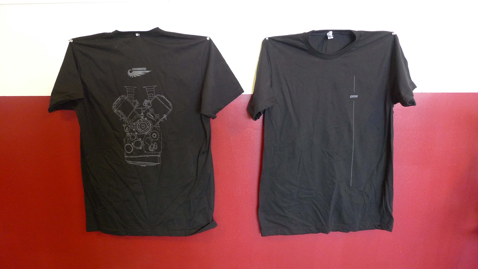
Back in action, now with T-shirts
Well, that was an extended absence. It was not too bad from my perspective since I was working on a motorcycle-related project. Now that the first stage of the TZ250 engine case project is done so I can get some time to get some of my bike project in. I'm sure my control arm material stock and programs are feeling neglected, but hey, that's life.
One point of good news is that the T-shirts have finally come in. I ended up using Metro Printing & Promotions because of their good turnaround and great pricing. Steve was a big help in getting the graphics sized and located properly. In keeping with the Made in USA theme of the project I aptly chose American Apparel t-shirts.
The shirts look great (apart form the wrinkles) and are super comfortable. Thanks again to Sacha Halenda at Form Five for the clean and elegant layout. I'll be sending out the first batch of shirts next week so all those who so generously gave to the cause can expect something in the mail soon. If anyone else is interested I have plenty of extras ready to ship. All donations are appreciated.
Finally, next week is a bike part week. I'll be definitely machining the upper control arm and hopefully getting the lower control arm done too. Posts and pics will follow.
That's all for now.
Chris
One point of good news is that the T-shirts have finally come in. I ended up using Metro Printing & Promotions because of their good turnaround and great pricing. Steve was a big help in getting the graphics sized and located properly. In keeping with the Made in USA theme of the project I aptly chose American Apparel t-shirts.
The shirts look great (apart form the wrinkles) and are super comfortable. Thanks again to Sacha Halenda at Form Five for the clean and elegant layout. I'll be sending out the first batch of shirts next week so all those who so generously gave to the cause can expect something in the mail soon. If anyone else is interested I have plenty of extras ready to ship. All donations are appreciated.
Finally, next week is a bike part week. I'll be definitely machining the upper control arm and hopefully getting the lower control arm done too. Posts and pics will follow.
That's all for now.
Chris
Saturday, February 18, 2012
Finally, someone hired me to make racebike parts!
For the past couple of months I've not had much time at all to devote to the bike project. Besides the usually unproductive weeks around the holiday season I had to do some rebuilding of the CNC mill's 4th axis after discovering an extremely worn worm wheel.
After the rebuild the 4th worked better than ever, which was great timing as I had a major machining project to do. And it was for a racebike!
Here in the US there are still a few diehard 250 GP guys. I can't blame them as a 250GP bike is the ultimate expression of economy of design second only to a 125 GP bike. One of these guys is Bruce Lind. He still runs them and runs them fast out there on the West Coast. Unfortunately, Yamaha's supply of crankcases is becoming limited, and combined with the flaw of receding bearing inserts, led him to try to have them converted to a billet design and do a short production run. With the cast cases failing after less than 2 seasons of use if a billet version could be made to last longer it would be worth a slight price premium. After a false start with a 2 stroke vendor used to parallel twins Bruce managed to find me through the USGPRU messaging boards. The USGPRU is the sanctioning body for FIM 125 and 250 GP racing here in the USA. They are doing a great job of integrating the new 4 strokes into the program while allowing people to continue running their 2 stroke bikes. Under the Team Incomplete banner I had a couple of very fun seasons running parts of their schedule on my RS125.
Its funny how these things work out. The only reason Bruce found me was that I was making an engine for the class that obsoleted his favorite machine! Anyway, Bruce saw the progress of the V4 project and decided it was worth a try to move the project over to me. After some brief discussions we agreed to terms and I started reverse engineering the cases. They are some pretty complex parts and I knew from the beginning that doing a straight copy would be extremely problematic due to the complexity of a part cast using internal cores.
Bruce also wanted to take advantage of the redesign to incorporate the latest porting and stuffing specifications. Unlike a 4 stroke engine with cams and valves that usually removes material when porting, a 2 stroke porter adds material to the inside of the crankcases to smooth flow between the reed cage and the transfer ports and to alter the compression that occurs in the cases. These cases were modified by a factory Yamaha race team so had a highly desirable and effective configuration.
The reverse engineering was more a redesign process using the same shaft and bore centers than a strict copy. In order to be able to machine the parts in a reasonable amount of time I had to convert a lot of the smooth cast surfaces into a faceted version that could be milled accurately and quickly.
Since we would be starting with quite large blocks of aluminum I also needed to find the most economical way to mill aluminum. Solid carbide end mills, while rigid and capable of high metal removal rates, tend to dull and wear out after a time and then the entire tool needs to be replaced, a wasteful process for such a premium material..
An alternative tool style is to use small carbide inserts mounted to a steel body. This style of Cutter allows you to quickly replace the dulled cutting edges with replacements at a minimal cost. A bit of online research led me to a Koroloy insert mill from Curtis Tool. Curtis was a big help in finding the right insert style for the part/machine combination and an extended toolholder for the deep pockets. These are pretty mean looking big carbide inserts that cut aluminum like the proverbial hot knife through butter.
I purchased 2 versions, a short 2" diameter version for the majority of the roughing, and a 1 1/2" version on a long extension for the deep gearbox pocketing.
Even with 6" of projection the cutters worked great with no chatter.
Here's a couple of shots of the assembly so far. The upper part is complete and the lower part is mostly complete. Once the final outer pocketing is done the parts will be assembled and then all the bearing bores finish machined as a matched pair.
The top part was made from a medium size billet that I bolted directly to the trunnion table:
After a whole lot of machining the resulting part emerged:
The lower part was made from an obscenely large chunk of aluminum. It was so tall I had to manually load tools because of clearance issues!
The final version of this part will weight less than 10% of the original billet weight. Most of the internal and detail work is done, all that is needed to finish is the external clearance routines then final boring.
These parts are by far the most complex billet pieces I've made so far. My V4 engine castings were of a similar complexity level but since they were castings there only was a relatively small amount of actual metal removal and the multiple part orientations were relatively easy to relate to each other. These pieces started out as a giant block and evolved though various orientations and machining operations. The enormous amount of metal removed made both the machine time much longer and that much harder to visualize. I was glad to get this far with no errors or machine crashes! I have a much greater respect for sculptures after doing this project.
If you still run a 250GP bike and need a new set of cases please contact Bruce and order up a set. The same goes for anyone that wants the coolest set of bookends ever. I'm almost done with the first set after which Bruce will assemble and test them. Once any final tweaks are integrated into the machining programs we'll go into production.
On the other hand, if you have a part or engine or entire bike that you'd like to reproduce, give me a call and we can work something out.
Once this set is finished I will get back on track and resume machining bike parts starting with the upper control arm. Hopefully that will happen next week.
Chris
After the rebuild the 4th worked better than ever, which was great timing as I had a major machining project to do. And it was for a racebike!
Here in the US there are still a few diehard 250 GP guys. I can't blame them as a 250GP bike is the ultimate expression of economy of design second only to a 125 GP bike. One of these guys is Bruce Lind. He still runs them and runs them fast out there on the West Coast. Unfortunately, Yamaha's supply of crankcases is becoming limited, and combined with the flaw of receding bearing inserts, led him to try to have them converted to a billet design and do a short production run. With the cast cases failing after less than 2 seasons of use if a billet version could be made to last longer it would be worth a slight price premium. After a false start with a 2 stroke vendor used to parallel twins Bruce managed to find me through the USGPRU messaging boards. The USGPRU is the sanctioning body for FIM 125 and 250 GP racing here in the USA. They are doing a great job of integrating the new 4 strokes into the program while allowing people to continue running their 2 stroke bikes. Under the Team Incomplete banner I had a couple of very fun seasons running parts of their schedule on my RS125.
Its funny how these things work out. The only reason Bruce found me was that I was making an engine for the class that obsoleted his favorite machine! Anyway, Bruce saw the progress of the V4 project and decided it was worth a try to move the project over to me. After some brief discussions we agreed to terms and I started reverse engineering the cases. They are some pretty complex parts and I knew from the beginning that doing a straight copy would be extremely problematic due to the complexity of a part cast using internal cores.
Bruce also wanted to take advantage of the redesign to incorporate the latest porting and stuffing specifications. Unlike a 4 stroke engine with cams and valves that usually removes material when porting, a 2 stroke porter adds material to the inside of the crankcases to smooth flow between the reed cage and the transfer ports and to alter the compression that occurs in the cases. These cases were modified by a factory Yamaha race team so had a highly desirable and effective configuration.
The reverse engineering was more a redesign process using the same shaft and bore centers than a strict copy. In order to be able to machine the parts in a reasonable amount of time I had to convert a lot of the smooth cast surfaces into a faceted version that could be milled accurately and quickly.
Since we would be starting with quite large blocks of aluminum I also needed to find the most economical way to mill aluminum. Solid carbide end mills, while rigid and capable of high metal removal rates, tend to dull and wear out after a time and then the entire tool needs to be replaced, a wasteful process for such a premium material..
An alternative tool style is to use small carbide inserts mounted to a steel body. This style of Cutter allows you to quickly replace the dulled cutting edges with replacements at a minimal cost. A bit of online research led me to a Koroloy insert mill from Curtis Tool. Curtis was a big help in finding the right insert style for the part/machine combination and an extended toolholder for the deep pockets. These are pretty mean looking big carbide inserts that cut aluminum like the proverbial hot knife through butter.
I purchased 2 versions, a short 2" diameter version for the majority of the roughing, and a 1 1/2" version on a long extension for the deep gearbox pocketing.
Even with 6" of projection the cutters worked great with no chatter.
Here's a couple of shots of the assembly so far. The upper part is complete and the lower part is mostly complete. Once the final outer pocketing is done the parts will be assembled and then all the bearing bores finish machined as a matched pair.
The top part was made from a medium size billet that I bolted directly to the trunnion table:
After a whole lot of machining the resulting part emerged:
The lower part was made from an obscenely large chunk of aluminum. It was so tall I had to manually load tools because of clearance issues!
The final version of this part will weight less than 10% of the original billet weight. Most of the internal and detail work is done, all that is needed to finish is the external clearance routines then final boring.
These parts are by far the most complex billet pieces I've made so far. My V4 engine castings were of a similar complexity level but since they were castings there only was a relatively small amount of actual metal removal and the multiple part orientations were relatively easy to relate to each other. These pieces started out as a giant block and evolved though various orientations and machining operations. The enormous amount of metal removed made both the machine time much longer and that much harder to visualize. I was glad to get this far with no errors or machine crashes! I have a much greater respect for sculptures after doing this project.
If you still run a 250GP bike and need a new set of cases please contact Bruce and order up a set. The same goes for anyone that wants the coolest set of bookends ever. I'm almost done with the first set after which Bruce will assemble and test them. Once any final tweaks are integrated into the machining programs we'll go into production.
On the other hand, if you have a part or engine or entire bike that you'd like to reproduce, give me a call and we can work something out.
Once this set is finished I will get back on track and resume machining bike parts starting with the upper control arm. Hopefully that will happen next week.
Chris
Thursday, February 16, 2012
Back from the void
I've been a bit busy on a cool project the past couple of months, something worthy of a post on this blog. Tomorrow I'll post some pics of the most complex billet parts I've made so far. And they are for a racing motorcycle.
Chris
Chris
Thursday, November 17, 2011
Finishing the steering stem
It was way back in July that I turned the blanks for various length steering stems. The various lengths allow me to adjust the amount of dive that happens under braking.
Here's where we left these parts:
Now these parts will be brought to the 4 axis mill and have the pivot holes and clamping faces machined. then i'll switch to another setup and trim and chamfer the ends.
The first step is holding the parts in a 3J collet on one end and with a dead center in the other to ensure the part axis is coincident with the mill 4th axis. That means that the zeroth step is to align the dead center to the 4th axis. I machined a round adapter that helps greatly in this process:
I then remove this mandrel, reinstall the dead center quill and then clamp a part:
To check the alignment I held a .0001" indicator in the mill spindle and rotated the 4th axis. the part was within .0003 TIR, which is an excellent runout for a 2nd operation clamping.
Now that the part is properly clamped and in alignment I can machine the features that mount the upper and lower control arms. the machining is 4 pocketing routines and 2 reamed hole routines ending with the almost complete part:
Repeat this a few times with appropriate modifications for the various lengths and i have a bunch of useable parts:
Now there is a simple cleanup operation to do on each side to round and smooth the ends. The part is held in the 4th axis in a 3J collet with the end just sticking out.
I profile the end, then chamfer it and repeat for both ends top and bottom:
The finished parts are pretty sweet lookin:
Especially when assembled in the spider:
That's one more part to cross of the to-do list. The front end is starting to take shape, i'm only missing the control arms which are next on the list of complex parts to do. I may try to squeeze in a few simple parts before that, let's see what the next week or 2 bring.
That's all for now.
Here's where we left these parts:
Now these parts will be brought to the 4 axis mill and have the pivot holes and clamping faces machined. then i'll switch to another setup and trim and chamfer the ends.
The first step is holding the parts in a 3J collet on one end and with a dead center in the other to ensure the part axis is coincident with the mill 4th axis. That means that the zeroth step is to align the dead center to the 4th axis. I machined a round adapter that helps greatly in this process:
I then remove this mandrel, reinstall the dead center quill and then clamp a part:
To check the alignment I held a .0001" indicator in the mill spindle and rotated the 4th axis. the part was within .0003 TIR, which is an excellent runout for a 2nd operation clamping.
Now that the part is properly clamped and in alignment I can machine the features that mount the upper and lower control arms. the machining is 4 pocketing routines and 2 reamed hole routines ending with the almost complete part:
Repeat this a few times with appropriate modifications for the various lengths and i have a bunch of useable parts:
Now there is a simple cleanup operation to do on each side to round and smooth the ends. The part is held in the 4th axis in a 3J collet with the end just sticking out.
I profile the end, then chamfer it and repeat for both ends top and bottom:
The finished parts are pretty sweet lookin:
Especially when assembled in the spider:
That's one more part to cross of the to-do list. The front end is starting to take shape, i'm only missing the control arms which are next on the list of complex parts to do. I may try to squeeze in a few simple parts before that, let's see what the next week or 2 bring.
That's all for now.
Subscribe to:
Posts (Atom)