We left off on the crankshafts with all the lathe operations being complete and all 4 parts being ready for the 4 axis mill work.
The next operation is to do the offset machining needed for the connecting rod journals. There are two techniques available: eccentrically mount the crankshaft in a special chuck on the connecting rod axis and turn the journal or mount the crankshaft on the main journals and eccentrically turn the conrod journal. The first option is easier to program but more difficult to fixture, is very unbalanced during machining, and requires part repositioning for each conrod throw. The 2nd option is more complicated from a programming perspective but is easier to fixture, is balanced, and needs no part repositioning. I chose the 2nd option as once the upfront programming work is done making multiples is easy and repeatable.
Due to the low cutting forces due to the aluminum test part material and a desire to get a sample part machined I opted to leave the outboard 4th axis support off. Machine time these days is limited and getting a sample part quickly was of prime importance.
The mill setup is as shown:

The first operations are simple pocketing to remove the majority of the material in the most efficient machining technique. Pocketing was done at increments of 90 degrees and ended up with squarish journals.


Once this stage was complete I moved on to the 2nd program which created the fully round journals. The video of this move is subtle but cool. The machine is performing a G3 arc in the YZ plane (G19) while the 4th axis is doing a rotary move from 0 to 360 degrees. The result is an eccentric true cylindrical surface with none of the approximation concerns usually associated with surface machining type toolpaths.

And this is a short movie of both journals.

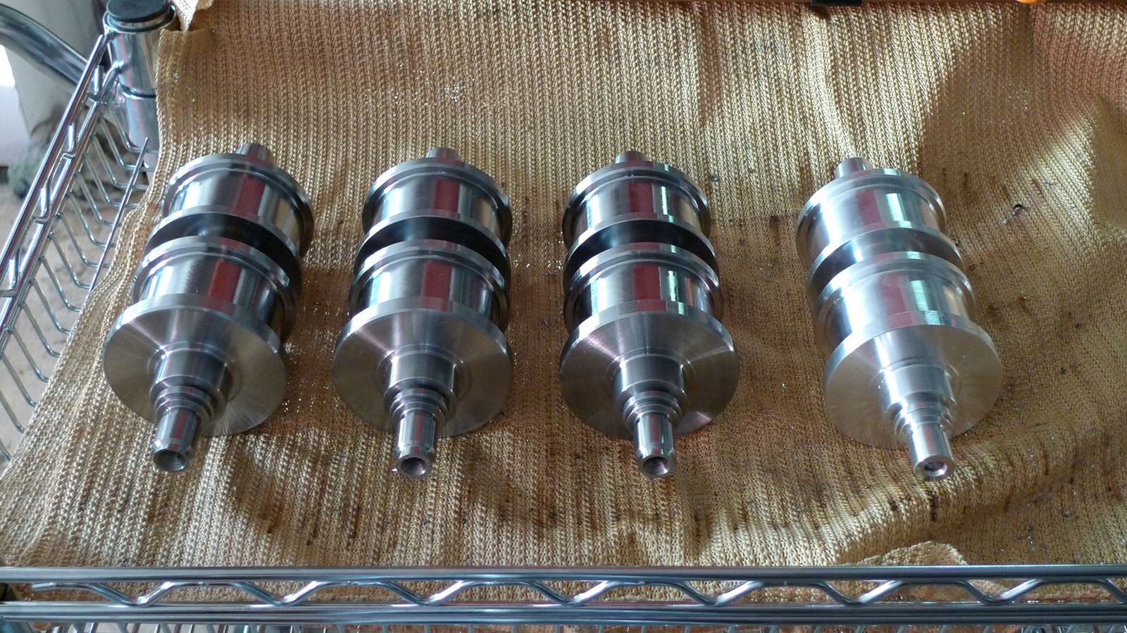
This part is being sent to a grinding house for finishing of the journals so the absolute tolerance and surface finish are not as crucial as long as there is enough stock left to clean up during grinding. After consulting with the grinder I am leaving .010" of stock on the main journals and .020" on the connecting rod journals as grinding allowance.
Now that I have a sample crankshaft we can test assemble a short block with the major rotating components: crank, conrods, pistons, and also trans and oil pump/drive components. Once we reach that stage there will be lots of pictures!
That's all for now.
Chris

Excellent posting. Really enjoying following your project. Thanks!
ReplyDeleteThanks! Its fun and once the engine actually runs will be a huge milestone. Soon!
ReplyDeleteChris
Looking good brother, welded heads will be delivered tomorrow.
ReplyDeleteCheers
Ask around work colleagues and acquaintances in your field if they can recommend a precision machining company to you.
ReplyDeleteI was amazed by your single and the work you carried out on it, particularly the engine you put the Ducati head on. Unfortunately those pages no longer seem available?
ReplyDeleteThis blog is incredible though and I can't wait to see the fully built bike!!
Shaun,
ReplyDeleteThanks for the post. A lot of the work on the single is still viewable at http://www.cosentinoengineering.com/index_files/Page430.htm but the ti-racing.com site is no longer up, sorry.
I'm hoping to be able to post some more soon so you'll have more to check out on the V4.
Regards,
Chris
Ah yes, thats some great stuff.
ReplyDeleteOnce the motor is running, will you be turning to the chassis etc.?
I am interested to see how the swingarm turns out, amongst other things...
I am so glad that you have taken the time to document and write about what you are doing, it's an awesome read and quite inspiring
I'm trying to get some chassis parts in progress in parallel to the engine but times are tight!
ReplyDeleteThe swingarm is being made by kolbmachine.com. hopefully he'll have some time in the coming weeks to make some good progress,
Regards,
chris