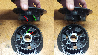
- The clutch cover had a sound dampening assembly in the cap that was about 3/4" thick, a pretty significant amount.
- The cam chain guides were retained with bolts using o-rings to prevent rattle.
- The primary drive gear had a spring loaded floating gear to eliminate gear rattle at low speeds
- The clutch had a thin section belleville spring on the clutch hub to keep the friction pack from rattling when disengaged.
After all that effort to reduce mechanical noise, they used roller cam chains instead of 'silent' cam chain. I wonder if the silent style chain was not strong enough.
Getting the side covers off, then removing the clutch and generator is one more layer of the onion off. The OEM slipper clutch had only 3 springs but were assisted by a significant self-locking design on the slipper clutch hub. Not only did the hub have a negative ramp that opened the clutch pack to create slippage when negative torque is applied, it also has a positive ramp which acts to tighten the pack pressure when slippage occurs when positive torque is applied.
Once all the covers and ancillary components were removed, what remained was what was really of interest: shaft center locations.
By careful measuring and use of 3D scanning techniques I will establish the relationships between the various shaft centers. This information will be transferred to CAD as a simple 2D sketch that can then be used as the basis of the new engine design
This may seem like a simple 2D drawing, but it contains most of the important engine dimensions has 'hidden' information which drives downstream relationships in the CAD model.
From the initial inspection it seems to make sense to use the following components/subsystems:
- cam drive system
- oil pump system
- generator/starter assembly
- cylinder head
- transmission
- shifter mechanism
- piston/cylinder liner
- crankcases
- crankshaft
- connecting rod
- counterbalance shaft
- water pump
- oil passage system
The water pump will be an external on-demand electric pump supplied by Davies Craig. I use this technology in the existing Rotacular with excellent results and temperature control with no need for duct tape on the radiator. Seeing how much space is taken by the water pump (2 stage gear reduction) and the thermostat/distribution manifold, I am surprised that Ducati did not go a electric route. They have the radiator, fan, shroud, and hose assembly design as a complete assembly that can be removed as a unit. Integrating an electric pump would be a snap and simplify the overall routing.
The other decision to make is which head to use, the horizontal or vertical one.
The vertical head as two robust mounts used for the subframe that could be repurposed for a front engine mount but the decision will be driven by which side the cam drive and generator systems are cleanest to integrate into.
Once all of these shaft centers and their components are measured and put into the new arrangement, the crankcases are designed by creating an envelope around the parts, adding thickness to it, then adding ribs and gussets for strength.
So a little measuring and a lot of thinking are on my to-do list for the next couple of weeks. I'll post updates as items become resolved.
Also, here is a nice gallery of disassembled Panigale engine pictures
Chris


Loving this build so far Chris. Fingers crossed it does come together this time (as compared to the V4 which I was certainly rooting for).
ReplyDeleteWhere did you get all the special jig bits to take the motor apart?
Cheers
Marc
Marc, thanks for your positive thoughts. This single will defintely come together, it is a more managable bite to chew. The V4 was a bit of a moonshot. Hopefully the single's success will bleed over to the V4 and we can get that running too!
ReplyDeleteI made whatever tools were needed for disassembly but did order a 'socket' for the crank cam drive nut since I am reusing that part and it is nice to have a durable tool for it. I also ordered a piston inserter tool to make compressing the rings easy.