Showing posts with label motorcycle race. Show all posts

Sunday, July 19, 2020

Engine Geometry Verification Part 1

Now that all the major details in engine design are finished, it is time to verify the center distances of all the shafts.  Once they are individually tested, I can start generating toolpaths.

First up is the cam chain run.  There is some flexibility here as the main drivers of the shape of the chain run are the fixed and pivoting cam chain guides, which are easily machined to any desired shape from nylon. I would like to reuse both OEM Panigale parts but not at the expense of a non-optimal solution.


The cylinder head has been moved away from the crank by nearly 1" (longer connecting rod) and there is also a significant (but classified) amount of cylinder offset, so the geometry of the chain run is different than in the OEM design.  This is complicated by the fact that the upper mounts for both guides are located in the cylinder head and are considered immovable.  The lower mounts are both located in the new crankcases so can be positioned as desired.

To check the chain path, a mock-up of the shaft and pivot centers was made using a plate of aluminum and  some spacers and shafts.

First thing that was needed was a 104 link chain due to the longer connecting rod.  Since my order of custom chains from IWIS has not arrived yet, a simple spliced version would suffice for this test.  A bit of grinding and pressing and presto, two short chains give their all to make one longer one.
Next, a scrap ground aluminum plate was the source for the main frame, and needed some holes in the appropriate locations, a job the Bridgeport was waiting for.
A few bushings for the shafts kept the Hardinge occupied for a few minutes.  I made Delrin bushings instead of plain reamed holes in the aluminum plate so I can spin this at a decent RPM to see actual chain dynamics and not have it seize up.
After a bit of assembly, the test-setup is ready for inspection.
The pivoting guide looks like it is properly contacting the chain but the fixed guide not so much, particularly at the top near the cam sprocket.
From my discussions with the IWIS tech engineer, this area needs to have slightly more engagement with the chain.  I just sent some images and questions to him but expect to have to make a new fixed guide that slightly increases the contact area in this top section of the fixed guide.  The part can be machined from a bar of Nylon 6/6 so is an easy fix to the situation.

While my questions are getting answered I can move on to verifying the starter drive gear train center distances.  This was a little more of a departure from the OEM design as I had to accommodate both a significantly different packaging arrangement, and a counter rotating crankshaft.

Details to follow.

Friday, July 17, 2020

Casting Process Successful!

I received a nice shipment from Curto containing 3 full sets of usable castings!  It is usually pretty cool when parts for a client's project come in but when the project is your own baby, the excitement is greatly magnified.  Imagine seeing a new dirt bike in front of a Christmas tree and you are in the right ballpark.

The combination of gating assistance from Curto and the 3D printed sand molds from Humtown resulted in parts with crisply defined features and just a bit of surface roughness, a traditional characteristic of the 3D sand printing process.  Though a bit rough, the finish was very consistent.  Think of it as a mini heatsink!


Both the pour and the post processing of the parts by Curto was excellent.  The T6 heat treat left no appreciable distortion at the gasket surface, and if I did not do the mold CAD myself, would not be able to tell where the feeders were attached.


 The high damping properties of magnesium and the internal and external ribs on the oil sump and left side cover (along with the hydrodynamic crank/counterbalance bearing system) will help keep transmission of internal mechanical engine sounds to a minimum and allow the intake howl and the exhaust growl to dominate the aural frequencies.
The clutch/generator cover's deep cylindrical shapes are themselves resistant to vibrational excitation, so less ribbing is needed here.  Internal features on the generator mount allow use of an unmodified Panigale stator with its wiring, crankcase seal, and waterproof connector.  It is a minor detail, but the stator is an electrical part subject to failure, so it is nice to be able to drop in an off-the-shelf replacement part.  The same goes for the voltage regulator, which is also an OEM part and easily accessible.

Having not worked directly with sand cast AZ-91-T6 Magnesium before,  I requested a piece of the runner/feeder system also be heat treated and sent along with the parts.  I will use this piece to do some machining speeds/feeds optimization, but more importantly to do some pull-out testing for the few M6 threaded inserts and for the oil drain plug in the oil sump and the M5 inserts for the clutch cover.  Magnesium is quite a soft material so I would rather not depend on threads created in it.  I will test both E-Z Loc and TimeSert inserts to see which works best.  TimeSerts are very low profile so maybe use them first and if there is a failure, there will still be room for an E-Z Loc.


Due to casting being a slightly unpredictable process, I was not sure if all the parts would be fully filled and usable but it turns out my fears were unfounded.  Curto's design assistance was top notch and with this completely successful pour, I now have 3 sets of castings.  They mesh up nicely with the 3 sets of billet blocks for crankcases, and enough 4340 VM steel for 3 sets of crank and counterbalance shafts.  A bit of ebay shopping later and it is possible to have 3 engines, and then a bit further, 3 bikes!

One last, unrelated item: last week I made a significant change to my original plan of using a hacked OEM Panigale ECU to do the engine and chassis management.  This did not go as planned and required some regrouping and rethinking, and in a week or so I will be able to go into some more detail on the new solution.

All right, time to stop typing and start doing!


Tuesday, June 16, 2020

Casting the Engine Side Covers and Oil Sump

I am really starting to gain some momentum on the engine part of the project.  Now that all the vendors for the various outsourcing needs have been contacted, parts and specifications discussed, quotes given, and deposits sent, the design really becomes frozen.

Crankcase and crankshaft posts will be coming shortly, this post deals with the engine side covers and oil sump for the semi-dry sump oiling system design.  The parts themselves are pretty straightforward and will be sand cast in AZ91 Magnesium alloy and heat treated to a T6 specification.


Why magnesium and why cast, instead of the billet aluminum I do so often?  Magnesium for weight and a nod to tradition, as the dark green Dow17 (or sometimes with gold paint) color is a traditional sign of a factory race engine.  I am a factory and this is a race engine!  Though it is not that strong, magnesium is very light, and for lightly loaded applications like engine covers, is a great, through pricey solution.  Why cast and not billet?  Pricing of magnesium billets for these parts is prohibitively expensive.  In this case, casting is the 'cost effective' approach!

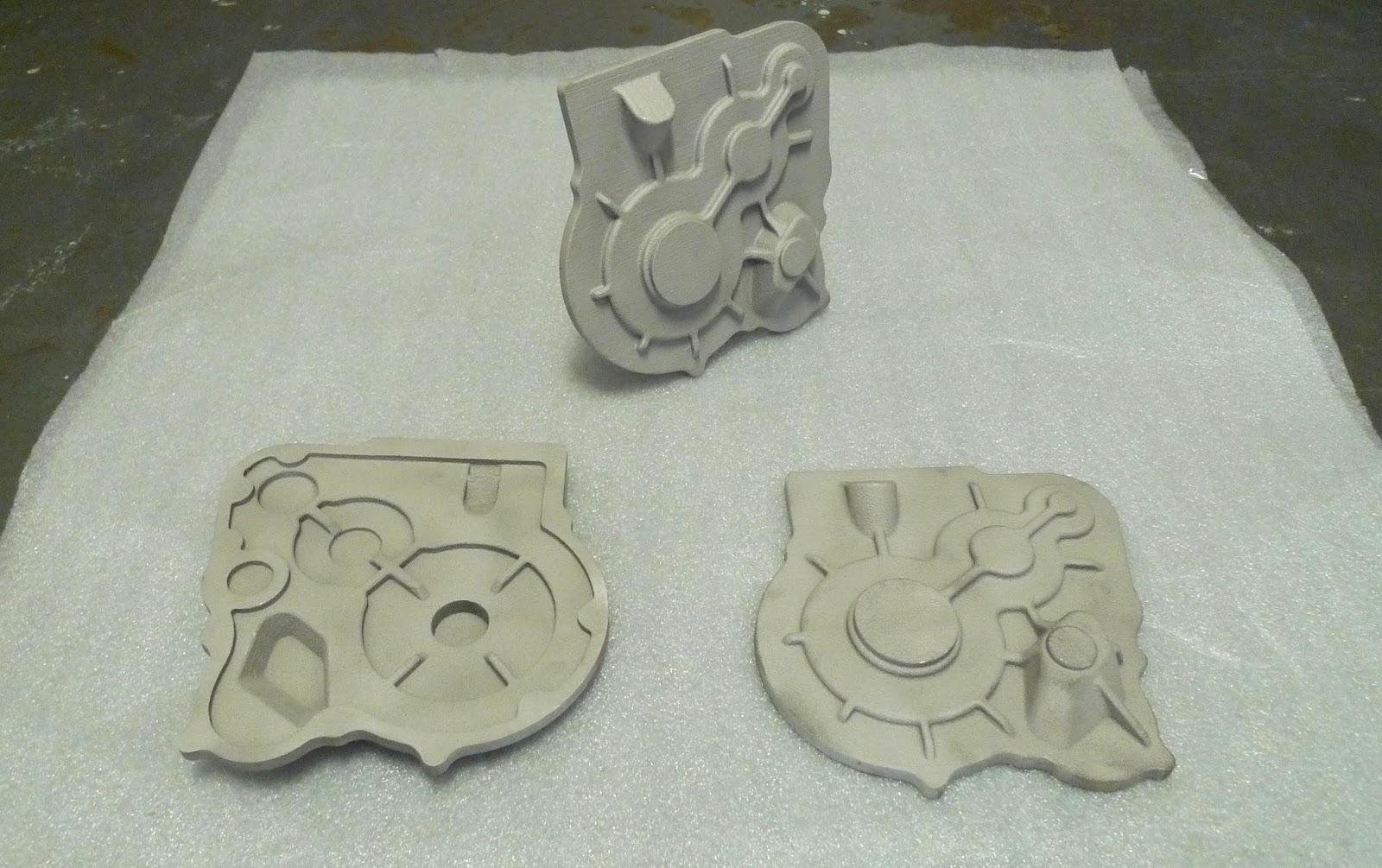
The process I am following is a very modern take on the ages-old sand casting technique.  Most of the recent improvements in sand cast prototyping have been using 3D CAD to generate accurate models, then use 3D printers to quickly create low cost patterns that would be used to create the sand molds.  The approach I am using goes one step further, the 3D CAD model is used to create a digital mold, that can then be printed directly in casting sand via very specialized (read expensive) 3d printing equipment.

These molds are being printed by Humtown Products, who provide pattern and moldmaking services using a variety of traditional and cutting edge technology.  They use an ExOne 3D sand printer that has two refrigerator-sized printing tanks that can print sand molds over 6 feet long!  Brandon from Humtown did the hand-holding with me to ensure the molds were prepared exactly as needed.


Imagine an inket printer crossed with a sandbox and you are not far away from this machine!  A layer of sand is applied by a precision scraper, the printhead sweeps past and sprays a specialized adhesive on the areas that are to become the mold.  It builds the part layer by layer (sound familiar?) and at the end the un-adhered sand is brushed away.   A good video can be seen at here.

Since these molds will be poured with magnesium, they need a special treatment to prevent the reactive liquid metal with the surface sand of the mold.  Potassium fluoroborate is mixed with the sand before printing to accomplish this.

These completed, treated 3D printed sand molds will be shipped to Curto-Ligonier Foundries Co. for the parts to be poured and heat treated to T6 condition.  Curto has extensive experience with both aluminum and magnesium sand casting for both the aerospace and motorsports industries.  They are not aware of it yet, but after this sub-project is successfully completed, I will spring my one-piece sand cast swingarm project on them!  Curto have been very helpful with overall gating design assistance, not to mention dealing with someone that has as many questions as I do!

Now on to the meat of the post:


The Generator Side Engine Cover:

-covers the generator rotor, counterbalance shaft gear, and clutch
-mating surface for clutch pack access
-mount for generator stator and wire routing

Starter Side Engine Cover:
-covers starter geartrain, cam chain drive, and shift lever mechanism
-access port for crank
-oil fill
-outboard seal support for shift lever shaft

Oil Sump:
-main oil reservoir
-secondary support for electric water pump

The cope and drag halves of the molds were manually created by referencing the existing part geometry.  The molds have pouring and riser openings in the top surface to ensure the parts fill and cool correctly without sink marks.
The molds are assembled like a Tetris game in the printer so that they can be made in the smallest vertical height to save both sand and printing time.

When printing is complete, the molds are cleaned, packed, and shipped off by truck to the foundry.  I will ask Brandon form Humtown and Jovan from Curto to take many pictures of the process for the follow-up blog post.  The printing should take a couple of weeks, and then a few more for pouring and heat treat, so hopefully in under 2 months we will all see a lot of pictures of perfectly filled cast magnesium parts!

Enough for 3 engines!

That's it for now.

Saturday, June 6, 2020

All Parties Heard From

Came in today to receive a nice email from the crankshaft vendor of choice, David at Marine Crankshaft, Inc.  He had reviewed my drawings and requests and agreed to take on the process of turning a rough-machined crankshaft blank into a ready-to-use part.

The plan is to use 5 1/2" diameter 4340 vacuum melt material from Yarde Metals in a normalized and tempered state (Rc28-34 for you techies) which will be machined in the lathe and mill, leaving adequate stock on all bearing surfaces.  The process will be very much like the process used for the V4 engine detailed here, here, here, here, and here, but with bigger, more rigid machine tools.  I'll then send the crank to Marine where they will heat treat, finish grind, detail oil holes, superfinish, then plasma nitride as the final step.  This will produce a crankshaft with extremely fine bearing journal finish, strong and ductile core section properties, harder/stronger shell properties, and an extremely hard and lubricious plasma nitrided final surface.  The last truly beautiful crank I saw was a Rick Schell Stage 4 crank for a TZ250.  It was so gorgeous you didn't want to put it inside crankcases.  I am hoping the Hypermono crank will elicit similar feelings.

The main dimensions of the crank (journals diameters, stroke) were retained from the Ducati part to make bearing sourcing a simple proposition but the other proportions were made to match the new single cylinder application.  The resulting design is short and rigid, two nice adjectives to use for a crankshaft.
I used as many of the design tricks for a high performance crankshaft as possible, including hollow rod journal, large bearing fillet radii, and tungsten slugs for balancing.

Determining the optimum engine balance factor was not straightforward.  The offset cylinder complicated the situation enough that a simple piston primary and secondary force analysis was not sufficient.  Again I called on the help of Tony Foale to determine the best approach.  One of his papers on engine balance  and his basic engine balance software were a good starting place.


Digging into his big bag of software tricks he was able to modify an existing program to take into account not only the basic piston primary and secondary forces, but the relative positions of the crank, piston axis, and counterbalance shaft.  He ran a few optimization studies and the results started flowing.  For a basic analysis a 50% balance factor on the crank and 50% on the counterbalance shaft produces the lowest overall engine vibration levels.  The optimized result was a few percent different than the basic simulation and, just as important, the balance weights are optimally not 180 from the throw, again off by a few degrees.  Even though 50/50 and 180/180 would have been good enough and resulted in a smooth engine, if I am going to go through all this trouble, why not make the parts to the optimal values instead of approximate ones?  There is no good answer not to!


The crank assembly is configured a little different than most crankshafts due to the idler gear being between the crankshaft and the clutch.  This gives me the same radial room on both ends of the crank for components.  As the design progressed and I shuffled components back and forth, the best overall layout ended up with the primary drive gear and generator on one end, and the timing wheel/starter clutch, starter gear, and cam drive sprocket on the other.


Most of these parts are Ducati OEM, no reason to reinvent the starter clutch or generator rotor.

Now that i have a definite path forward on all the outsourced components the last bits of material will be ordered, CAD files finalized and frozen, and toolpath generation started.  Lots of clicking ahead for me in the next several weeks but after that, fabrication starts in earnest.  That will produce much more exciting pictures and videos!