Came in today to receive a nice email from the crankshaft vendor of choice, David at Marine Crankshaft, Inc. He had reviewed my drawings and requests and agreed to take on the process of turning a rough-machined crankshaft blank into a ready-to-use part.
The plan is to use 5 1/2" diameter 4340 vacuum melt material from Yarde Metals in a normalized and tempered state (Rc28-34 for you techies) which will be machined in the lathe and mill, leaving adequate stock on all bearing surfaces. The process will be very much like the process used for the V4 engine detailed here, here, here, here, and here, but with bigger, more rigid machine tools. I'll then send the crank to Marine where they will heat treat, finish grind, detail oil holes, superfinish, then plasma nitride as the final step. This will produce a crankshaft with extremely fine bearing journal finish, strong and ductile core section properties, harder/stronger shell properties, and an extremely hard and lubricious plasma nitrided final surface. The last truly beautiful crank I saw was a Rick Schell Stage 4 crank for a TZ250. It was so gorgeous you didn't want to put it inside crankcases. I am hoping the Hypermono crank will elicit similar feelings.
The main dimensions of the crank (journals diameters, stroke) were retained from the Ducati part to make bearing sourcing a simple proposition but the other proportions were made to match the new single cylinder application. The resulting design is short and rigid, two nice adjectives to use for a crankshaft.
I used as many of the design tricks for a high performance crankshaft as possible, including hollow rod journal, large bearing fillet radii, and tungsten slugs for balancing.
Determining the optimum engine balance factor was not straightforward. The offset cylinder complicated the situation enough that a simple piston primary and secondary force analysis was not sufficient. Again I called on the help of Tony Foale to determine the best approach. One of his papers on engine balance and his basic engine balance software were a good starting place.
Digging into his big bag of software tricks he was able to modify an existing program to take into account not only the basic piston primary and secondary forces, but the relative positions of the crank, piston axis, and counterbalance shaft. He ran a few optimization studies and the results started flowing. For a basic analysis a 50% balance factor on the crank and 50% on the counterbalance shaft produces the lowest overall engine vibration levels. The optimized result was a few percent different than the basic simulation and, just as important, the balance weights are optimally not 180 from the throw, again off by a few degrees. Even though 50/50 and 180/180 would have been good enough and resulted in a smooth engine, if I am going to go through all this trouble, why not make the parts to the optimal values instead of approximate ones? There is no good answer not to!
The crank assembly is configured a little different than most crankshafts due to the idler gear being between the crankshaft and the clutch. This gives me the same radial room on both ends of the crank for components. As the design progressed and I shuffled components back and forth, the best overall layout ended up with the primary drive gear and generator on one end, and the timing wheel/starter clutch, starter gear, and cam drive sprocket on the other.
Most of these parts are Ducati OEM, no reason to reinvent the starter clutch or generator rotor.
Now that i have a definite path forward on all the outsourced components the last bits of material will be ordered, CAD files finalized and frozen, and toolpath generation started. Lots of clicking ahead for me in the next several weeks but after that, fabrication starts in earnest. That will produce much more exciting pictures and videos!
Saturday, June 6, 2020
Friday, June 5, 2020
Details, Details, Details.
There seems to be plenty of empty time these days so there is plenty of time to obsess over some bike design details! I'm sort of going a little stir crazy and am finding it hard to be really productive, so please bear with a scattershot blog post. I'll be covering a bunch of stuff, from parts status to design details, to fabrication prep.
The last, last minute change is that we have decided to go from a 1299 piston/cylinder assembly which is a 116mm piston in a thin steel liner, to the 1199 piston cylinder assembly, which is a 112mm piston in a thicker aluminum liner. Seems that the 1199 is the basis for all the race development, like 2 ring pistons for less frictional drag. The lost 50cc of displacement will be more than made up for in less friction and better breathing.
Now that the important dimensions have now been set in stone, purchase orders have been issued and the bank account is cringing in submission:
The engine CAD model is undergoing subtle refinements as time allows. Current state is good enough to freeze and start making chips but there seems to be no sense rushing things so I am revisiting details that, while satisfactory from a pure engineering perspective, just don't have that elegant feel to the design solution. These areas are, of course, few and far in between. ;)
I have contracted with Curto-Ligonier Foundries to sand cast the two side covers and the oil sump in AZ91 magnesium. Curto will be providing all the feeding, gating and sprue design information which I will use to create cope and drag parts of the molds for sand casting.
The sand molds themselves will be 3D printed sand that the metal will be poured directly into. The sand molds will be 3D printed by Humtown Products. Brandon Lamoncha there has been a big help in gathering the various details needed for the process.
As the engine nears design completion, I can focus on the rest of the bike. Since the chassis and suspension are already fully detailed, I can progress to details like air intake routing, airbox, and electrical components.
The dual air intake path threads through both small triangles formed at the crest of the frame then merges, has a filter mount, then enters the airbox. Its volume is approximately 9.5l, plenty big to tune the Helmholtz resonance frequency to help boost the mid-range power.
For the air runners, I determined the minimum air intake size, doubled it, then used Creo's advanced 3d surfacing features to create duct with a curvature-continuous walls and a linearly increasing cross-sectional area. This helps slow the air from road speed to 0 with minimal losses, ensuring max static pressure. Even though ram air benefit is pretty small for a bike that can only do about 160mph, it makes sense to try to get what you can if it does not get in the way of something else that is more important.
The air intake system leaves plenty of room for a nice size filter at the front of the airbox housing. The various electronics modules (ECU, water pump control, coil, IMU, etc.) will live on to and around the base of the ram air ducts. I am not sure if there will be brackets molded into the ducts or a complex 3D printed housing that has a few discrete mounting points. Those details have a minor enough impact on the surronding parts that I can push them back until the first test assembly phase, where details like this are best resolved.
That's about it for now. Forthcoming posts will cover the sand mold design process and the resultant castings, and the start of crankcase and crankshaft machining.
Hope you are all staying sane during this craziness.
The last, last minute change is that we have decided to go from a 1299 piston/cylinder assembly which is a 116mm piston in a thin steel liner, to the 1199 piston cylinder assembly, which is a 112mm piston in a thicker aluminum liner. Seems that the 1199 is the basis for all the race development, like 2 ring pistons for less frictional drag. The lost 50cc of displacement will be more than made up for in less friction and better breathing.
Now that the important dimensions have now been set in stone, purchase orders have been issued and the bank account is cringing in submission:
- custom length connecting rods from Carrillo
- custom length high performance roller cam chain from IWIS
- 6061-T6511 aluminum blocks for crankcases
The engine CAD model is undergoing subtle refinements as time allows. Current state is good enough to freeze and start making chips but there seems to be no sense rushing things so I am revisiting details that, while satisfactory from a pure engineering perspective, just don't have that elegant feel to the design solution. These areas are, of course, few and far in between. ;)
I have contracted with Curto-Ligonier Foundries to sand cast the two side covers and the oil sump in AZ91 magnesium. Curto will be providing all the feeding, gating and sprue design information which I will use to create cope and drag parts of the molds for sand casting.
The sand molds themselves will be 3D printed sand that the metal will be poured directly into. The sand molds will be 3D printed by Humtown Products. Brandon Lamoncha there has been a big help in gathering the various details needed for the process.
As the engine nears design completion, I can focus on the rest of the bike. Since the chassis and suspension are already fully detailed, I can progress to details like air intake routing, airbox, and electrical components.
The dual air intake path threads through both small triangles formed at the crest of the frame then merges, has a filter mount, then enters the airbox. Its volume is approximately 9.5l, plenty big to tune the Helmholtz resonance frequency to help boost the mid-range power.
For the air runners, I determined the minimum air intake size, doubled it, then used Creo's advanced 3d surfacing features to create duct with a curvature-continuous walls and a linearly increasing cross-sectional area. This helps slow the air from road speed to 0 with minimal losses, ensuring max static pressure. Even though ram air benefit is pretty small for a bike that can only do about 160mph, it makes sense to try to get what you can if it does not get in the way of something else that is more important.
The air intake system leaves plenty of room for a nice size filter at the front of the airbox housing. The various electronics modules (ECU, water pump control, coil, IMU, etc.) will live on to and around the base of the ram air ducts. I am not sure if there will be brackets molded into the ducts or a complex 3D printed housing that has a few discrete mounting points. Those details have a minor enough impact on the surronding parts that I can push them back until the first test assembly phase, where details like this are best resolved.
That's about it for now. Forthcoming posts will cover the sand mold design process and the resultant castings, and the start of crankcase and crankshaft machining.
Hope you are all staying sane during this craziness.
Labels:
3d printing,
casting,
ducati,
engine,
hypermono,
machining,
Moto2,
panigale,
transmission
Saturday, April 18, 2020
Trying to Keep Sane During the Insanity
So what to do during social isolation while the economy comes screeching to a halt like a Ducati GP bike with warm carbon rotors? Besides clean and organize the shop, that is? Work on the Hypermono design!
After a few days helping various NYC groups design and set up for mass manufacture of plastic PPE masks, I was able to get some solid time on bike design.
Here's the current status:
The ram air ducts and subframe tubes are placeholders. The fuel tank is partly designed, including the fuel pump/regulator mounting and internal feed lines to the injectors, but the external surfaces await design refinement. Capacity will be somewhere north of 3.5gal. As a naked rolling chassis it looks a bit better (IMO).
Really good progress has been made in all areas, especially in having the engine nearly ready for CAM programming. I am putting a lot of thought into making discrete sub-assemblies and having the bike both easy to assemble and easy to work on at the track. The bike is very dense and packaging everything that is needed is becoming a greater and greater challenge but thankfully not much is left to add. Detail areas like battery tray, ECU, sensor, relay, and electrical components mounting have all been either resolved or a definite path to resolution has been seen.
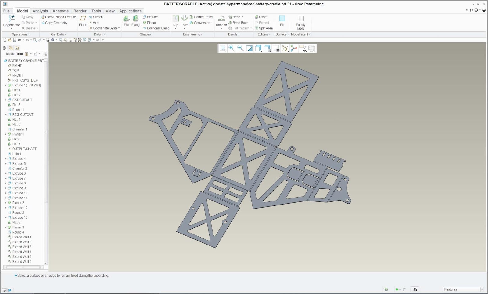
The battery tray is an example of the detailing. It mounts on the engine above the transmission area and below the fuel tank/airbox:
It is a discrete sub-assembly designed around an AntiGravity AG-801 8-cell Lithium battery and houses the battery, vibration isolation, regulator/rectifier, starter relay, a ground post, and mounting points for several harness connectors. The connections to the battery are short and shielded form the elements so should provide reliable starting. All electrical components are OEM parts with full waterproofing for ease of servicing and complete reliability in all weather conditions.
The mount is made from a piece of plasma cut and formed titanium sheet. Why titanium? Why not! It is hard to beat for light weight in thin sheet structures. Thin aluminum sheet is weak and easy to ding. Steel is heavy. Titanium is strong, lighter than steel, and its high UTS makes it very resistant to dings and permanent deformation. In a situation where all-out stiffness is not needed, it is hard to beat Ti.
The engine is nearing completion on the design side and almost ready to move to CAM programming.
I am really happy with how the entire design came out. Initially, the crankcases were going to be horizontally split. I'm not sure why, but it always seemed to me to be the style that a single cylinder engine would lend itself to. As the design progressed it became very clear that this was not the case! (no pun intended) The parts just did not want to be horizontally split. I was trying to ignore the assembly difficulties that horizontal splitting presented, but after the 3rd or 4th area where a really clever machining solution would be needed to manufacture the cases, I threw in the towel and went for a vertical split.
Once that happened, progress was swift. Oh, hell, I guess just go with the flow!
The engine internals are about as dense as the rest of the bike. I was worried that placing the counterbalance shaft between the crank and transmission would result in a long engine. Shortening the shift mechanism and making a compact counterbalance shaft, I was able to nest them side by side. This kept the cases compact at the expense of having to fabricate a custom shift drum and shift forks. A small price to pay to keep the heart of the bike as optimized as possible.
Both the crank and the counterbalance shaft have tungsten weights to keep the rotating radii as small as possible yet still give the needed balance factors. The crank balance masses are held in bores in the counterweights by Smally retaining rings while the counterbalance mass is radially bolted on, à la F1 crankshafts. All of the engine sensors are OEM Ducati parts to avoid sourcing problems.
Another area that was given some attention is the radiator assembly and area just behind the front wheel. Due to the setup characteristics of my linkage front end, the front wheel does not move rearwards when the suspension compresses, leaving me a bit of room to tidily fit in come more components.
I was able to draw up some nice multi-functional brackets (again in plasma cut Ti) to mount the radiator, overflow tank, cooling fan, and wire harness routing for the electric water pump, quickshifter sensor, gear position sensor, crank position sensor, and oil pressure sender. On the other side of the bike, a small Setrab oil cooler with high flow fittings mounts to the lower frame rail with 3D printed brackets and completes the bike's cooling needs.
Since cooling the oil was mentioned, I may as well show the oiling circuit. Oil is the lifeblood of an engine. Keep it cool and an engine can last forever. Let it overheat and the engine will quickly die a horrible death. My aim is for this bike to be ultra-reliable, so it needs to have a very robust oil system that is guaranteed to provide as much clean and cool oil as the engine could even need. I think the result will fit the bill. It is short and simple and uses a spin-on filter that is located so it won't drench the exhaust or anything else when being changed. The Ducati scavenge and pressure stages are reused so overall flow rates should be up to the task. The scavenge stage operates on the sealed crank/c'balance/piston underside volume to create a partial vacuum to aid in ring sealing and avoiding crankcase ventilation problems. It pushes the oil sucked from the crank chamber out onto the transmission, providing some of its lubrication, which then splashes into the sump. From the sump, the pressure stage takes it and pushes it through the filter, and out of the engine to the oil cooler.
The Setrab cooler is plumbed with high-flow -8AN fittings to reduce pressure loss.
The oil returns to the engine directly into the main oil galley, which has direct drillings to feed the main bearings, counterbalance bearings, and the Panigale cam chain and head oil feed lines. There is also a small hole that is the piston oil jet, which is crucial for cooling high performance, large bore engines.
So far, I think all the bases have been covered and the engine will be a reliable powerhouse. Big predictions, and I can only hope that the reality is all I am hoping it will be.
Since the original racing schedule is completely out the window for obvious reasons, things are not in a big rush. I'm going to continue on refining details for a couple more weeks before freezing the design and moving into the fabrication stage, starting with CAM programming for lots and lots of parts.
Hopefully, sometime soon after that I will be able to announce progress on the visual design aspects, including bodywork, color, and lots of little details that make a motorcycle pleasing to look at. Though I do think the naked bike is beautiful, it does need something more. Those soft details are not something I do well and hopefully the project will attract someone with the passion and skill to pull it off. Spread the word!
That's all for now. I am looking forward to human ingenuity kicking the ass of the Covid19 virus and allowing us to get back to our normal lives. In the meantime, everyone be healthy.
Chris
After a few days helping various NYC groups design and set up for mass manufacture of plastic PPE masks, I was able to get some solid time on bike design.
Here's the current status:
The ram air ducts and subframe tubes are placeholders. The fuel tank is partly designed, including the fuel pump/regulator mounting and internal feed lines to the injectors, but the external surfaces await design refinement. Capacity will be somewhere north of 3.5gal. As a naked rolling chassis it looks a bit better (IMO).
Really good progress has been made in all areas, especially in having the engine nearly ready for CAM programming. I am putting a lot of thought into making discrete sub-assemblies and having the bike both easy to assemble and easy to work on at the track. The bike is very dense and packaging everything that is needed is becoming a greater and greater challenge but thankfully not much is left to add. Detail areas like battery tray, ECU, sensor, relay, and electrical components mounting have all been either resolved or a definite path to resolution has been seen.
The battery tray is an example of the detailing. It mounts on the engine above the transmission area and below the fuel tank/airbox:
It is a discrete sub-assembly designed around an AntiGravity AG-801 8-cell Lithium battery and houses the battery, vibration isolation, regulator/rectifier, starter relay, a ground post, and mounting points for several harness connectors. The connections to the battery are short and shielded form the elements so should provide reliable starting. All electrical components are OEM parts with full waterproofing for ease of servicing and complete reliability in all weather conditions.
The mount is made from a piece of plasma cut and formed titanium sheet. Why titanium? Why not! It is hard to beat for light weight in thin sheet structures. Thin aluminum sheet is weak and easy to ding. Steel is heavy. Titanium is strong, lighter than steel, and its high UTS makes it very resistant to dings and permanent deformation. In a situation where all-out stiffness is not needed, it is hard to beat Ti.
The engine is nearing completion on the design side and almost ready to move to CAM programming.
I am really happy with how the entire design came out. Initially, the crankcases were going to be horizontally split. I'm not sure why, but it always seemed to me to be the style that a single cylinder engine would lend itself to. As the design progressed it became very clear that this was not the case! (no pun intended) The parts just did not want to be horizontally split. I was trying to ignore the assembly difficulties that horizontal splitting presented, but after the 3rd or 4th area where a really clever machining solution would be needed to manufacture the cases, I threw in the towel and went for a vertical split.
Once that happened, progress was swift. Oh, hell, I guess just go with the flow!
The engine internals are about as dense as the rest of the bike. I was worried that placing the counterbalance shaft between the crank and transmission would result in a long engine. Shortening the shift mechanism and making a compact counterbalance shaft, I was able to nest them side by side. This kept the cases compact at the expense of having to fabricate a custom shift drum and shift forks. A small price to pay to keep the heart of the bike as optimized as possible.
Both the crank and the counterbalance shaft have tungsten weights to keep the rotating radii as small as possible yet still give the needed balance factors. The crank balance masses are held in bores in the counterweights by Smally retaining rings while the counterbalance mass is radially bolted on, à la F1 crankshafts. All of the engine sensors are OEM Ducati parts to avoid sourcing problems.
Another area that was given some attention is the radiator assembly and area just behind the front wheel. Due to the setup characteristics of my linkage front end, the front wheel does not move rearwards when the suspension compresses, leaving me a bit of room to tidily fit in come more components.
I was able to draw up some nice multi-functional brackets (again in plasma cut Ti) to mount the radiator, overflow tank, cooling fan, and wire harness routing for the electric water pump, quickshifter sensor, gear position sensor, crank position sensor, and oil pressure sender. On the other side of the bike, a small Setrab oil cooler with high flow fittings mounts to the lower frame rail with 3D printed brackets and completes the bike's cooling needs.
Since cooling the oil was mentioned, I may as well show the oiling circuit. Oil is the lifeblood of an engine. Keep it cool and an engine can last forever. Let it overheat and the engine will quickly die a horrible death. My aim is for this bike to be ultra-reliable, so it needs to have a very robust oil system that is guaranteed to provide as much clean and cool oil as the engine could even need. I think the result will fit the bill. It is short and simple and uses a spin-on filter that is located so it won't drench the exhaust or anything else when being changed. The Ducati scavenge and pressure stages are reused so overall flow rates should be up to the task. The scavenge stage operates on the sealed crank/c'balance/piston underside volume to create a partial vacuum to aid in ring sealing and avoiding crankcase ventilation problems. It pushes the oil sucked from the crank chamber out onto the transmission, providing some of its lubrication, which then splashes into the sump. From the sump, the pressure stage takes it and pushes it through the filter, and out of the engine to the oil cooler.
The Setrab cooler is plumbed with high-flow -8AN fittings to reduce pressure loss.
The oil returns to the engine directly into the main oil galley, which has direct drillings to feed the main bearings, counterbalance bearings, and the Panigale cam chain and head oil feed lines. There is also a small hole that is the piston oil jet, which is crucial for cooling high performance, large bore engines.
So far, I think all the bases have been covered and the engine will be a reliable powerhouse. Big predictions, and I can only hope that the reality is all I am hoping it will be.
Since the original racing schedule is completely out the window for obvious reasons, things are not in a big rush. I'm going to continue on refining details for a couple more weeks before freezing the design and moving into the fabrication stage, starting with CAM programming for lots and lots of parts.
Hopefully, sometime soon after that I will be able to announce progress on the visual design aspects, including bodywork, color, and lots of little details that make a motorcycle pleasing to look at. Though I do think the naked bike is beautiful, it does need something more. Those soft details are not something I do well and hopefully the project will attract someone with the passion and skill to pull it off. Spread the word!
That's all for now. I am looking forward to human ingenuity kicking the ass of the Covid19 virus and allowing us to get back to our normal lives. In the meantime, everyone be healthy.
Chris
Tuesday, March 3, 2020
Finalizing Engine Geometry
When starting with a clean sheet engine design it can be easy to get lost in the permutations of the various main parameters. Since I am not going fully clean sheet and instead using a complete cylinder head from an existing engine, some of the important parameters can be reused from the donor engine's values: in this case a bore of 116mm and a stroke of 60.8mm. Just a bit oversquare. This leaves a couple of other major parameters open for interpretation: conrod length and, less common, cylinder offset.
How connecting rod length affects engine dynamics is pretty straightforward: the longer it is, the less secondary vibration you have at the expense of a taller overall engine. With my linkage front suspension, the chassis area near where a traditional headstock would be is pretty open, so a taller engine is not a packaging problem.
Using a non-zero cylinder offset, a Désaxé engine, has a more complex affect on an engine's dynamics as introduces a significant asymmetry into the piston motion, which can have far-reaching consequences.
This image shows how cylinder offset can affect piston lateral forces which generate significant internal friction. My design choices of a long rod and cylinder offset should provide a low friction, smooth running engine.
Setting up a dynamic simulation, validating it, and sifting through the results would be a very time consuming proposition, so I did the next best thing, turned to a subject mater expert. Actually, since I got a good answer with minimal effort, this was the best choice!
The subject matter expert in this case is Tony Foale, most likely one of the top 10 experts on motorcycle dynamics worldwide. Unlike the other 9 experts, Tony is not sequestered in someone's factory, he is open with his knowledge and willing to answer any questions. His website, https://motochassis.com/, is a great source of information on characterizing motorcycle dynamic behavior. His book, Motorcycle Handling and Chassis Design, (check out page 9-23) is required reading for anyone wanting to understand or improve motorcycle operation and performance. His thorough analysis of the motorcycle turn-in process is second to none. He also has several software packages available for overall chassis and suspension setup that are in use by race teams worldwide.
A quick email to Tony explained my project, and as always he was willing to help. He 'just happened to have' some software already written to do force and vibration analysis of singles. Well, some people crochet for a hobby.
A few simulations and back-and-forths and the results were 'an offset of close to 10 mm will reduce piston frictional losses by a useful amount over the planned rev range.' The following graphs were provided to support this conclusion. The absolute values of the graphs are less important than the difference between the zero offset and offset cases.
Graph showing axial piston pressure load. As expected, not much difference between the two cases. Graph showing axial inertia loading for the two cases. Note how the curves are not symmetrical around TDC and BDC. This is purely a geometric effect of the offset cylinder centerline. It also has the benefit of increasing the intake/power cycles to about 182 degrees of crank rotation and the exhaust/compression cycles to 178 degrees. This introduces a slight amount of Atkinson cycle efficiencies without dilution of the intake charge, which is great.
The combination of the two top graphs which shows a small reduction in the maximum axial piston loading, which is nice.
Graph showing the piston lateral loading, the main reason for this analysis. In this case the max loading is not as critical (as long as it is not excessive) but the 'area under the curve', which indicates the total frictional loss, is. In this case the area is noticeably reduced from the non-offset to the offset, which was the goal of the analysis. So, as previously said 'an offset of close to 10 mm will reduce piston frictional losses by a useful amount over the planned rev range.' Excellent!
To get more detailed information would have required an order of magnitude more effort in simulating the piston motion and secondary effects and still be subject to experimental verification. As it is, this information was extremely helpful and allows me to move on to detail design of the engine support components. Thanks, Tony!
How connecting rod length affects engine dynamics is pretty straightforward: the longer it is, the less secondary vibration you have at the expense of a taller overall engine. With my linkage front suspension, the chassis area near where a traditional headstock would be is pretty open, so a taller engine is not a packaging problem.
Using a non-zero cylinder offset, a Désaxé engine, has a more complex affect on an engine's dynamics as introduces a significant asymmetry into the piston motion, which can have far-reaching consequences.
This image shows how cylinder offset can affect piston lateral forces which generate significant internal friction. My design choices of a long rod and cylinder offset should provide a low friction, smooth running engine.
Setting up a dynamic simulation, validating it, and sifting through the results would be a very time consuming proposition, so I did the next best thing, turned to a subject mater expert. Actually, since I got a good answer with minimal effort, this was the best choice!
The subject matter expert in this case is Tony Foale, most likely one of the top 10 experts on motorcycle dynamics worldwide. Unlike the other 9 experts, Tony is not sequestered in someone's factory, he is open with his knowledge and willing to answer any questions. His website, https://motochassis.com/, is a great source of information on characterizing motorcycle dynamic behavior. His book, Motorcycle Handling and Chassis Design, (check out page 9-23) is required reading for anyone wanting to understand or improve motorcycle operation and performance. His thorough analysis of the motorcycle turn-in process is second to none. He also has several software packages available for overall chassis and suspension setup that are in use by race teams worldwide.
A quick email to Tony explained my project, and as always he was willing to help. He 'just happened to have' some software already written to do force and vibration analysis of singles. Well, some people crochet for a hobby.
A few simulations and back-and-forths and the results were 'an offset of close to 10 mm will reduce piston frictional losses by a useful amount over the planned rev range.' The following graphs were provided to support this conclusion. The absolute values of the graphs are less important than the difference between the zero offset and offset cases.
Graph showing axial piston pressure load. As expected, not much difference between the two cases. Graph showing axial inertia loading for the two cases. Note how the curves are not symmetrical around TDC and BDC. This is purely a geometric effect of the offset cylinder centerline. It also has the benefit of increasing the intake/power cycles to about 182 degrees of crank rotation and the exhaust/compression cycles to 178 degrees. This introduces a slight amount of Atkinson cycle efficiencies without dilution of the intake charge, which is great.
The combination of the two top graphs which shows a small reduction in the maximum axial piston loading, which is nice.
Graph showing the piston lateral loading, the main reason for this analysis. In this case the max loading is not as critical (as long as it is not excessive) but the 'area under the curve', which indicates the total frictional loss, is. In this case the area is noticeably reduced from the non-offset to the offset, which was the goal of the analysis. So, as previously said 'an offset of close to 10 mm will reduce piston frictional losses by a useful amount over the planned rev range.' Excellent!
To get more detailed information would have required an order of magnitude more effort in simulating the piston motion and secondary effects and still be subject to experimental verification. As it is, this information was extremely helpful and allows me to move on to detail design of the engine support components. Thanks, Tony!
Sunday, March 1, 2020
A Good Season Opener at Roebling Road!
Its been a little while since the last post but I have not been idle. A little client work and some volunteer machining for the Cooper Union FASE team has kept me a little busy. I did manage to get a race weekend in and am getting back on Hypermono design ASAP.
After the past couple of events with the bike not running, I was a little reluctant to pack up and ship out to Roebling Road, near Savannah, Georgia, for an early season race weekend. The bike has been troublesome lately....... Since Peter's Dynojet dyno was back in working condition, a little dyno work on the injection maps was little more than wheeling the bike 20 feet to the dyno room. For the first few runs it was running bretty badly. The AF sensor was out of range and the bike was not cooperating. A little imagination, some internet searching, and some excel cut and paste got me to a decently running map.
The bike still breaks up here and there but in general it was a big improvement on the previous map with partial mapping not being a light switch anymore.
The long ride from NYC to Savannah was pretty uneventful with Jamie taking driving duties while Kerry and I swapped out co-piloting and pointing out Cracker Barrel locations.
Thursday morning we were greeted by a cold rainy day. I usually don't mind wet riding but when temps are in the 40s I have to draw the line. We all rescheduled our practice day to Friday, I did a little fiberglass patchwork to repair transport damage, and they we hit the road back to our AirBnB. Had a good diner followed by some drinks at the Pinky Masters with some of Kerry's friends, who made another appearance at the end of the weekend.
Friday was also cold, but no rain so we waited out the cold and did a few afternoon sessions to shake the cobwebs out. Unfortunately, I had lots of cobwebs and would spend the rest of the weekend trying to get out from under them. Jamie's mother arrived midway through the day and was a welcome paddock guest.
Saturday greeted us with a layer of frost on everything in the pits.
Morning practice was again written off as we huddled in the sprinter with the heat on. Lunch was provided by Jamie's mom, which was greatly appreciated. The afternoon warmed up a little and as I lined up on the race was ruing my lack of practice. The race was uneventful but as the laps wound down felt better and better on the bike. Roebling is a weird track, there is not much braking, and none of it hard. I was coming to the end of the main straight at about 125mph or so and hitting the brakes, then realizing that I didn't have to. Lap after lap this went on as I struggled to get into a decent groove. All too soon the race was over and I was left wanting more.
Sunday was pretty much a carbon copy of Saturday. Cold, cold morning and slightly better afternoon. Did some more laps feeling slow, then a couple that were maybe not slow, then the checkered flag flew and the weekend was done.
Overall, I was satisfied to finally get the bike on the track for some trouble-free running. If not for the cold weather, I would have had a lot more track time and had a better chance of getting back into the racing groove. As it is, I was satisfied to have done both races with no bike problems.
I was so happy with how the season opened that as we met up with Kerry's friends at Riverside Tattoo Parlor I decided a tattoo was in order. There was no peer pressure involved. Lauren did a great job slightly adapting my logo to a tattoo and inking it on my skin forever.
Now to think of what tattoo #2 will be.
Will have some more posts on the Hypermono coming soon, finalizing some main engine parameters and ordering long lead-time parts.
After the past couple of events with the bike not running, I was a little reluctant to pack up and ship out to Roebling Road, near Savannah, Georgia, for an early season race weekend. The bike has been troublesome lately....... Since Peter's Dynojet dyno was back in working condition, a little dyno work on the injection maps was little more than wheeling the bike 20 feet to the dyno room. For the first few runs it was running bretty badly. The AF sensor was out of range and the bike was not cooperating. A little imagination, some internet searching, and some excel cut and paste got me to a decently running map.
The bike still breaks up here and there but in general it was a big improvement on the previous map with partial mapping not being a light switch anymore.
The long ride from NYC to Savannah was pretty uneventful with Jamie taking driving duties while Kerry and I swapped out co-piloting and pointing out Cracker Barrel locations.
Thursday morning we were greeted by a cold rainy day. I usually don't mind wet riding but when temps are in the 40s I have to draw the line. We all rescheduled our practice day to Friday, I did a little fiberglass patchwork to repair transport damage, and they we hit the road back to our AirBnB. Had a good diner followed by some drinks at the Pinky Masters with some of Kerry's friends, who made another appearance at the end of the weekend.
Friday was also cold, but no rain so we waited out the cold and did a few afternoon sessions to shake the cobwebs out. Unfortunately, I had lots of cobwebs and would spend the rest of the weekend trying to get out from under them. Jamie's mother arrived midway through the day and was a welcome paddock guest.
Saturday greeted us with a layer of frost on everything in the pits.
Morning practice was again written off as we huddled in the sprinter with the heat on. Lunch was provided by Jamie's mom, which was greatly appreciated. The afternoon warmed up a little and as I lined up on the race was ruing my lack of practice. The race was uneventful but as the laps wound down felt better and better on the bike. Roebling is a weird track, there is not much braking, and none of it hard. I was coming to the end of the main straight at about 125mph or so and hitting the brakes, then realizing that I didn't have to. Lap after lap this went on as I struggled to get into a decent groove. All too soon the race was over and I was left wanting more.
Sunday was pretty much a carbon copy of Saturday. Cold, cold morning and slightly better afternoon. Did some more laps feeling slow, then a couple that were maybe not slow, then the checkered flag flew and the weekend was done.
Overall, I was satisfied to finally get the bike on the track for some trouble-free running. If not for the cold weather, I would have had a lot more track time and had a better chance of getting back into the racing groove. As it is, I was satisfied to have done both races with no bike problems.
I was so happy with how the season opened that as we met up with Kerry's friends at Riverside Tattoo Parlor I decided a tattoo was in order. There was no peer pressure involved. Lauren did a great job slightly adapting my logo to a tattoo and inking it on my skin forever.
Now to think of what tattoo #2 will be.
Will have some more posts on the Hypermono coming soon, finalizing some main engine parameters and ordering long lead-time parts.
Wednesday, January 15, 2020
Structured Light Scanning is Cool!
After the caliper and plug technique used for the crankcase centers, watching Peter scan the cylinder head, throttle body, exhaust downtube, and oil pickup tube was like peeking into some wonderful future where all you had to do was press a button and presto, scan!
Actually, its nothing like 'press a button and presto', not much is. Peter has spent a lot of time and effort getting his scanning setup to provide repeatable results. Wikipedia has a bunch of details on the process here. The short of it is you have a projector and two cameras that are in a fixed orientation. The projector projects a pattern of changing scale onto the object to be scanned. The two cameras each see a different perspective of the pattern projected on the surface of the scanee, and through many billions of calculations, generates a 3D surface by reverse engineering the distorted pattern back to the flat one.
The pattern is projected at varying scales to aid in the process. The part to be scanned is sprayed with a white powder to enhance the contrast and increase accuracy. The DAVID software interface helps align multiple scans, delete duplicates, stitch it all together and do generally anything you need to get a watertight mesh.
A couple of hours of scanning and then a couple of more of processing resulted in some models with excellent fidelity to the originals.
The scan results were as good with the rest of the parts:
I can now import the mesh files into Creo and use the vertices as references for axes, planes, and datum curve features for the rest of the assembly to mate to.
The rest of the assembly then mates to it and the engine starts to take shape.
Now the cylinder head and piston can be located in the chassis in the start of the process of achieving the desired center of gravity positioning. Placement of the shaft centers and ancillary components is in process and once finalized, the skin of the crankcases starts to be generated. The next couple of weeks will be a combination of CAD positioning, napkin and computer calculations, and some decent eyeballing, to get what I feel is the optimum layout.
Two missing parts, the cam chain guides, will be mechanically scanned using a Romer digitizing arm and then redrawn natively in CAD in the next episode.
Actually, its nothing like 'press a button and presto', not much is. Peter has spent a lot of time and effort getting his scanning setup to provide repeatable results. Wikipedia has a bunch of details on the process here. The short of it is you have a projector and two cameras that are in a fixed orientation. The projector projects a pattern of changing scale onto the object to be scanned. The two cameras each see a different perspective of the pattern projected on the surface of the scanee, and through many billions of calculations, generates a 3D surface by reverse engineering the distorted pattern back to the flat one.
The pattern is projected at varying scales to aid in the process. The part to be scanned is sprayed with a white powder to enhance the contrast and increase accuracy. The DAVID software interface helps align multiple scans, delete duplicates, stitch it all together and do generally anything you need to get a watertight mesh.
A couple of hours of scanning and then a couple of more of processing resulted in some models with excellent fidelity to the originals.
The scan results were as good with the rest of the parts:
I can now import the mesh files into Creo and use the vertices as references for axes, planes, and datum curve features for the rest of the assembly to mate to.
The rest of the assembly then mates to it and the engine starts to take shape.
Now the cylinder head and piston can be located in the chassis in the start of the process of achieving the desired center of gravity positioning. Placement of the shaft centers and ancillary components is in process and once finalized, the skin of the crankcases starts to be generated. The next couple of weeks will be a combination of CAD positioning, napkin and computer calculations, and some decent eyeballing, to get what I feel is the optimum layout.
Two missing parts, the cam chain guides, will be mechanically scanned using a Romer digitizing arm and then redrawn natively in CAD in the next episode.
Wednesday, January 8, 2020
Measuring the Crankcase Shaft Locations
Seeing how few of the original crankcase features will be carried over to the new cases a full 3D scan of them is not necessary.
It is surprising how little information is needed. The dimensions of primary importance are:
I'll start with the primary drive side which has the primary and oil pump shaft centers.
ODs measured.
Measuring of the various centers.
Now on to the generator side that has the starter drive shafts. Yes, a starter motor! No more lugging around a car battery and external starter to get the beast started, just press the magic button. Oh, I can't wait!!!!!!!
The starter motor was not long enough to get a good measurement so I turned up a close fitting plug and used that instead.
Of secondary importance is the shifter drum and linkage axis locations. These are of secondary importance because if needed they can be replaced with custom components. I would prefer to use the OEM parts but if they force a more important component to move or some chassis parameter to change, then I would rather make new ones that are exactly what is needed instead of compromising.
This is not all the information that I need to design the cases, but it is all the information I need to start to design the cases!
Tomorrow I will use a Romer scanning arm to generate the profiles and mounting hole locations of the two cam chain guides and cylinder head gasket. Stay tuned!
It is surprising how little information is needed. The dimensions of primary importance are:
- crank to transmission input shaft distance
- transmission shaft spacing
- crank to oil pump intermediate gear distance
- oil pump intermediate gear to oil pump shaft distance
- crank to starter intermediate gear spacing
- starter intermediate gear to starter motor spacing
- head stud bolt and pin spacing
I'll start with the primary drive side which has the primary and oil pump shaft centers.
ODs measured.
Measuring of the various centers.
Now on to the generator side that has the starter drive shafts. Yes, a starter motor! No more lugging around a car battery and external starter to get the beast started, just press the magic button. Oh, I can't wait!!!!!!!
The starter motor was not long enough to get a good measurement so I turned up a close fitting plug and used that instead.
Of secondary importance is the shifter drum and linkage axis locations. These are of secondary importance because if needed they can be replaced with custom components. I would prefer to use the OEM parts but if they force a more important component to move or some chassis parameter to change, then I would rather make new ones that are exactly what is needed instead of compromising.
This is not all the information that I need to design the cases, but it is all the information I need to start to design the cases!
Tomorrow I will use a Romer scanning arm to generate the profiles and mounting hole locations of the two cam chain guides and cylinder head gasket. Stay tuned!
Subscribe to:
Posts (Atom)